RFL Auxiliary Hybrid Chassis RFL Electronics Inc.
March 29, 2005 5 (973) 334-3100
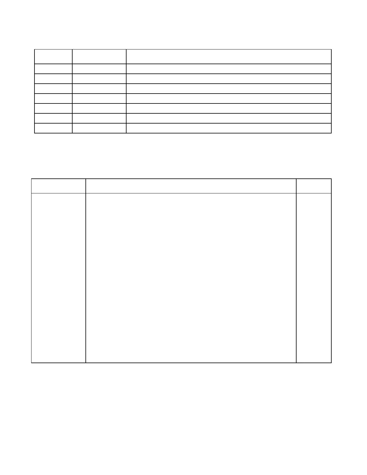
Table 1. Controls and indicators, X-Hybrid Module
Component
Designator
Name/Description Function
J1 Jumper Should always be in the A position.
TP3 Test point Line High (orange)
TP4 Test point Line Low (orange)
TP5 Test point Receive High (green)
TP6 Test point Receive low (yellow)
TP7 Test point Send High (red)
TP8 Test point Send Low (white)
Table 2. Replaceable parts, X-Hybrid module
Assembly No. 106630-1 and –2
Circuit Symbol
(Figs. 2 & 3)
Description Part
Number
F1
J1
L1
L2
P1
R13, 14
TP3, 4
TP5
TP6
TP7
TP8
MISCELLANEOUS COMPONENTS
Fuse, SLO-BLO, 10A, 32V, 3AG
Connector, header, single, 3CKT
Transformer, hybrid, 50 ohm, XMIT
106630-1
106630-2
Transformer, hybrid, 50 ohm, XMIT
106630-1
106630-2
Connector, JK, male, 64 contact, DIN
Resistor, wirewound, 100Ω, 5%, 10W
Test point terminal, orange
Test point, green
Test point, yellow
Test point, red
Test point, white
10758
32802 3
55768
55768
55768
55769
98457
100 795
98441 3
38116 5
38116 8
38116 2
38116 1
 Loading...