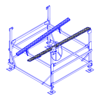
PRE-LIFTING CHECKLIST
The lift and related equipment must be thoroughly inspected prior to each use. Only those who have read and understood
this entire manual and related equipment manuals are qualified to do this inspection. This checklist is to be used as a
guideline in conjunction with the maintenance and inspection procedures outlined in this manual. It is recommended that the
inspection be maintained as a permanent record.
Insure the lift installation will clear all power lines and obstructions.
Insure all structural members of the lift are free of defects and damage that may affect the integrity.
Insure that an electric drive, if used, has been inspected and installed by a certified electrician in accordance with local
electrical codes. A Ground Fault Circuit Interrupter (G.F.C.I.) must be installed by your electrician and work properly.
Insure that any user or dealer installed locking devices have been removed before operating the lift.
Operate the lift first without, and then with, your boat on the platform to test the operation of both the lift and the
winch.
Insure the boat is properly positioned on the lift before doing any raising or lowering.
Insure the lift is not being used beyond its rated capacity.
Insure any drain plug is in place on the boat before launching.
Conduct the wire rope inspection procedure described in Chapter 5 at least monthly.
Insure the leg pins connect the vertical legs to the adjustable legs. Insure the leg height has been properly adjusted
according to the water depth.
Insure the frame and platform fastenings are tight.
Insure the lower diagonal braces are installed in each corner.
Insure the frame is level and square according to the dimensions shown in Figure 3-6, Chapter 3.
Insure the cable end loops of the load and spreader tubes are fastened to the bracket at the bottom of each vertical leg.
Insure the cable studs opposite the cable end loops in the platform assembly are tight. If tightening is needed, follow
the sequence described in Section 3.8 of Chapter 3. Then tighten the jam nuts to the cable nuts to lock the position.
Insure the winch is securely fastened to vertical leg “A”.
Insure the handwheel has been attached to the winch hubplate.
Insure the spinner knob is attached to the handwheel using the preassembled hardware.
Insure the A-B load tube cable stud is fastened to leg B to enable winch operation.
Insure set screw securing wire rope end to the drum is tight and in good condition.
When facing the front of the handwheel, insure that the wire rope winds and unwinds from the left side of the winch.
This reeving will raise the platform when the handwheel is turned clockwise, and lower the platform when the
handwheel is turned counterclockwise. The brake pawl must click, meaning the brake is operative.
Insure the guards are in place before operating the winch.
Insure the plastic caps are installed onto the tops of the vertical legs and the ends of the upper short horizontal tubes.



 To Next Page