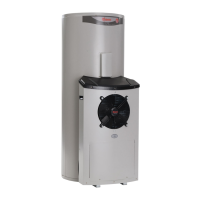
HEAT PUMP AND TANK ASSEMBLY
23
ASSEMBLY PROCEDURE
Warning: The heat pump must be assembled, plumbed and filled with water prior to power being
connected and switched on.
The following procedure should be followed to properly place the heat pump module in position and connect
to the storage tank:
1. Remove all packaging and position the storage tank in its intended location.
The storage tank must be positioned at least 100 mm from the wall. If a minimum clearance of 100 mm
is not allowed for, the heat pump module will not be able to be completely connected to the storage tank.
The water connections may be on either the left or right hand side, parallel to the wall.
Step 1
position storage tank at least 100 mm from the wall
2. Remove the two screws securing the lower front cover to the storage tank.
Remove the lower front cover from the storage tank.
Step 2 Step 3
remove screws withdraw the power cable
from lower front cover and tank sensor cable
3. Withdraw the power cable and tank sensor cable, housed behind the lower front cover, from the
opening.
 Loading...