HEAT PUMP AND TANK ASSEMBLY
29
21. Insert the tank sensor cable plug to the connector on the underside of the control box.
The plug is polarised and can only be inserted one way.
Ensure the plug fully engages the locking feature on the connector.
22. Insert the four pin power cable plug to the connector on the underside of the control box.
The plug is polarised and can only be inserted one way.
SK6502 AD A4 5/08
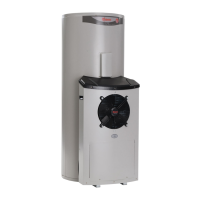
CONTROL BOARD HEAT PUMP - 325L
WITH SENSOR CABLE & POWER CABLE
TANK SENSOR
CABLE PLUG
POWER CABLE
PLUG
Steps 21 and 22
connect power cable and tank sensor cable
23. Complete final positioning of the water heater.
Ensure the heat pump module is firmly seated on the slab or solid base.
24. Connect the cold water supply and the hot water pipe work to the water heater.
Connect the temperature pressure relief valve and its drain line.
Refer to “Connections – Plumbing” on page 31.
 Loading...