EasyManua.ls Logo

Rheem 80PS Series - User Manual

Rheem 80PS Series
40 pages
Print Icon
To Next Page IconTo Next Page
Loading...
92-24161-61-01
SUPERSEDES 92-24161-61-00
INSTALLATION INSTRUCTIONS
FOR INDUCED DRAFT GAS FURNACES
80PS UPFLOW/HORIZONTAL SERIES
80LS DOWNFLOW SERIES
U.L. recognized fuel gas and CO (carbon monoxide) detectors are recommended in
all applications, and their installation should be in accordance with the
manufacturer’s recommendations and/or local laws, rules, regulations, or customs.
Upflow Models Downflow Models
Model Number Input (Btu) Tons Model Number Input (Btu) Tons
80PS05EAR** 50,000 3 80LS05EAR** 50,000 3
80PS05NAR** 50,000 3 80LS07EBR** 75,000 4
80PS07EBR** 75,000 3 80LS07EAR** 75,000 3
80PS07NBR** 75,000 3 80LS10EBR** 100,000 3
80PS07EER** 75,000 4 80LS10ECR** 100,000 5
80PS07NER** 75,000 4 80LS10EDR** 100,000 5
80PS10EBR** 100,000 3 80LS12EDR** 125,000 5
80PS10ECR** 100,000 4.5 80LS15EDR** 150,000 5
80PS10EDR** 100,000 5
80PS10NDR** 100,000 5
80PS12EDR** 125,000 5
80PS15EDR** 150,000 5
Question and Answer IconNeed help?

Do you have a question about the Rheem 80PS Series and is the answer not in the manual?

Overview

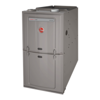
This document describes the installation, operation, and maintenance of a gas furnace, specifically focusing on models designed for upflow/horizontal and downflow applications.

Function Description:

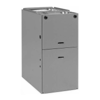
The device is a gas furnace designed for residential heating. It operates by burning natural gas or propane to heat air, which is then circulated throughout a building to provide warmth. The furnace is certified as a Category I furnace, allowing for vertical venting with type B-1 vent pipe or common venting. It is designed to be highly efficient, with an Annual Fuel Utilization Efficiency (AFUE) of 78% or higher, indicating good energy conversion. The furnace is designed to be compact, with a height of only 34 inches, making it suitable for various installation locations.

Important Technical Specifications:

The manual provides tables for various models, detailing their input BTU, output BTU, and tonnage. For example, upflow/horizontal models range from 50,000 BTU input (3 tons) to 150,000 BTU input (5 tons). Downflow models have similar ranges.

  • Clearances to Combustible Material: Specific clearances are provided for top, bottom, back, and sides (left and right) for both upflow/horizontal and downflow models. These clearances vary based on the input BTU and whether a special base is used for combustible floor installations. For instance, a 50,000 BTU upflow/horizontal model requires 1 inch top, 0 inch bottom, 1 inch back, and 4 inches on the right side.
  • Gas Supply: The furnace requires an adequate pipe size and proper supply and manifold gas pressure. For natural gas, the maximum supply pressure is 10.5" W.C. and manifold pressure is 3.5" W.C. For LP gas, the maximum supply pressure is 13" W.C. and manifold pressure is 10" W.C. Gas pipe capacity tables are provided to ensure correct sizing based on BTU input and pipe length.
  • Electrical: The furnace requires correct line supply voltage, proper power supply polarity (for electronic ignition), and a correct furnace ground to the electrical panel. Control voltage and DC microamp flame signal (for hot surface ignition units) are also specified. Wiring diagrams are included for both upflow/horizontal and downflow models, showing connections to the control board, thermostat, and various components like the inducer, blower, and gas valve.
  • Venting: Vent pipe diameter and length must comply with CSA tables. The venting material must also be appropriate. The manual specifies requirements for lining masonry chimneys, adequate clearance from combustibles, and proper negative pressure readings in the vent. Vent pipe attaching holes must be predrilled in the draft inducer collar to prevent damage.
  • Combustion Air: Proper sources and opening sizes for combustion air are critical. The manual details requirements for indoor and outdoor combustion air, including calculations for free area based on BTU input and ceiling height. Specific instructions are given for non-attic and attic combustion air pull, including figures illustrating configurations with horizontal and vertical inlets/outlets.
  • Airflow: Airflow tables are provided for both upflow/horizontal and downflow models, detailing external static pressure, blower motor HP, and CFM at various static pressures for different speeds (low, med-low, med-high, high). These tables are crucial for ensuring proper air temperature rise and efficient operation.
  • Filter Sizes: Filter sizes vary by furnace input BTU and jacket size. For example, a 50,000 BTU furnace with a 14" jacket requires a 12" x 15" x 1" filter.

Usage Features:

  • Installation Checklist: A comprehensive checklist is provided to ensure all aspects of installation are correctly addressed, from gas supply and electrical connections to venting and combustion air.
  • High Altitude Installations: Specific instructions and tables are provided for installations at elevations above 2000 ft, where the furnace input rating must be adjusted. This involves re-calculating burner orifices and adjusting manifold gas pressure.
  • LP Conversion: Instructions are included for converting the furnace from natural gas to LP gas, which involves replacing the pressure regulator spring and the burner orifices.
  • NOx Models: For furnaces equipped with NOx inserts, instructions are given for removing and re-installing the inserts.
  • Start-Up Procedure: Detailed steps for lighting the furnace, including checking for gas leaks, setting the thermostat, and verifying proper operation of the main burner.
  • Blower Timings: Instructions for setting blower timings (OFF delays) using jumpers on the electronic control board.
  • Airflow Measurement: Procedures for measuring air temperature rise and external static pressure to ensure the furnace is operating within specifications.
  • Field Installed Option Accessories: Information on compatible accessories such as electronic air cleaners, humidifiers, and fossil fuel kits.

Maintenance Features:

  • Filter Replacement: Filters should be checked monthly and replaced or cleaned as needed. The manual includes figures illustrating filter retention rods and filter and rod assembly for both upflow/horizontal and downflow installations.
  • Roll-Out Safety Switches: The furnace is equipped with safety switches to protect against roll-out conditions in the burner compartment. If tripped, these switches will shut down the furnace. Instructions are provided for resetting them.
  • Pressure Switch: The furnace includes a pressure switch that monitors pressure conditions within the furnace vent system.
  • Troubleshooting Flowchart: A detailed flowchart is provided to diagnose and resolve common issues related to furnace operation, including problems with ignition, steady run, and post-purge.
  • Lubrication: The inducer blower motor and induced draft motor are pre-lubricated and do not require further attention.
  • Cleaning: The blower assembly, heat exchanger, and other components should be periodically cleaned by a qualified installer to maintain efficiency and indoor air quality.
  • Vent System Inspection: Regular inspection of the vent system for obstructions, blockages, or signs of corrosion is crucial, especially during replacement installations.

Rheem 80PS Series Specifications

General IconGeneral
BrandRheem
Model80PS Series
CategoryFurnace
LanguageEnglish

Related product manuals