12
12
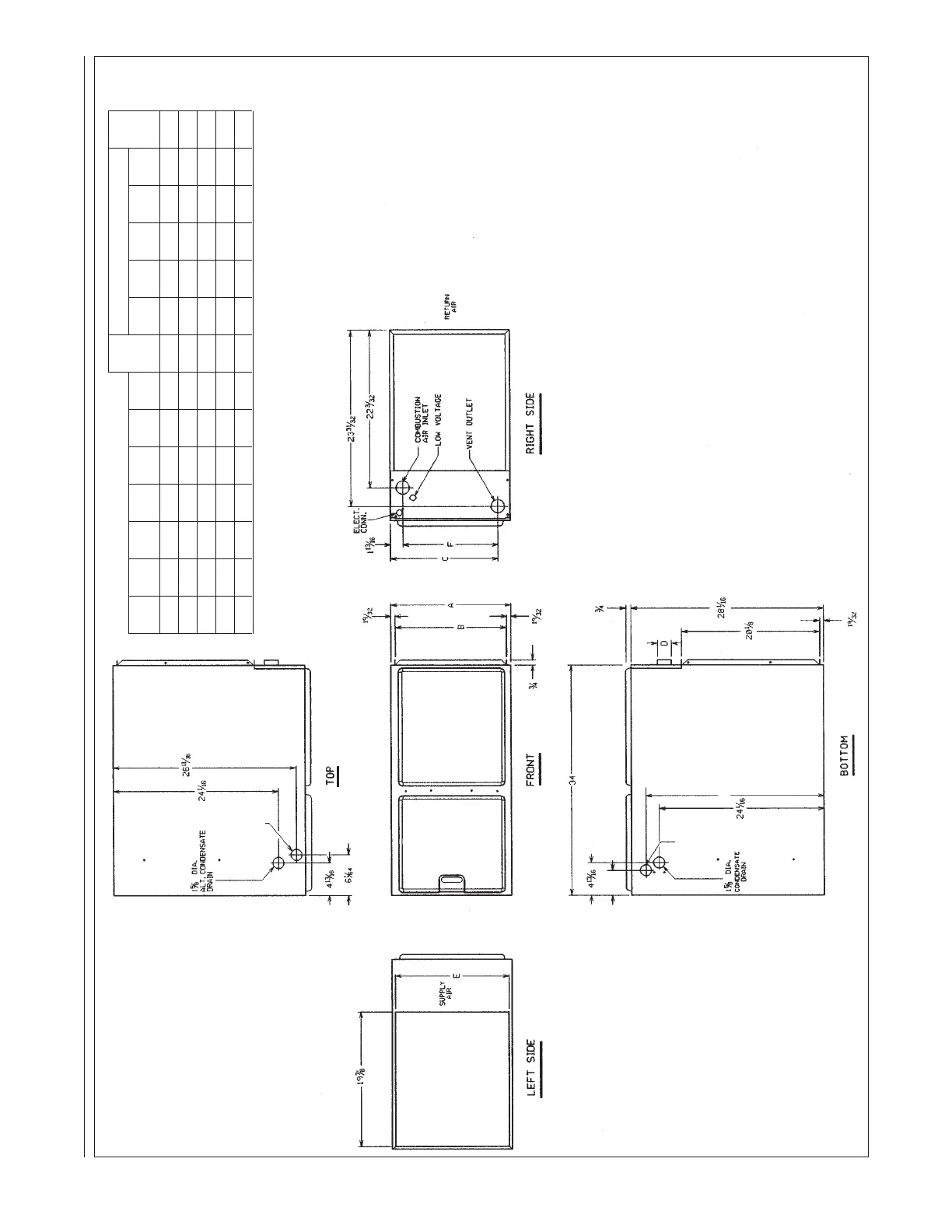
FIGURE 8
CLEARANCE TO COMBUSTIBLES, HORIZONTAL UNITS
I520
DOWNFLOW MODELS MINIMUM CLEARANCE (IN.)
LEFT RIGHT SHIP
MODEL A B C D E F
SIDE SIDE
BACK TOP FRONT VENT
WGTS
04 17
1
⁄2 16
11
⁄32 15
5
⁄8 2 16
5
⁄8 13
7
⁄8 0 0 0 1 2* 0 111
06 17
1
⁄2 16
11
⁄32 15
5
⁄8 2 16
5
⁄8 13
7
⁄8 0 0 0 1 2* 0 117
07 21 19
27
⁄32 19
3
⁄16 2 20
1
⁄8 17
3
⁄8 0 0 0 1 2* 0 137
09 21 19
27
⁄32 19
3
⁄16 2 20
1
⁄8 17
3
⁄8 0 0 0 1 2* 0 148
10 24
1
⁄2 23
11
⁄32 22
5
⁄8 2 23
5
⁄8 20
5
⁄8 0 0 0 1 2* 0 160
*A service clearance of at least 24 inches is recommended in front of all furnaces.
IMPORTANT: This furnace is not approved or recommended for
installation on its back, with access doors facing upwards.
25
13
⁄16
2 DIA.
ALT. GAS
CONNECTION
4
3
⁄8
2 DIA.
GAS
CONNECTION

 Loading...