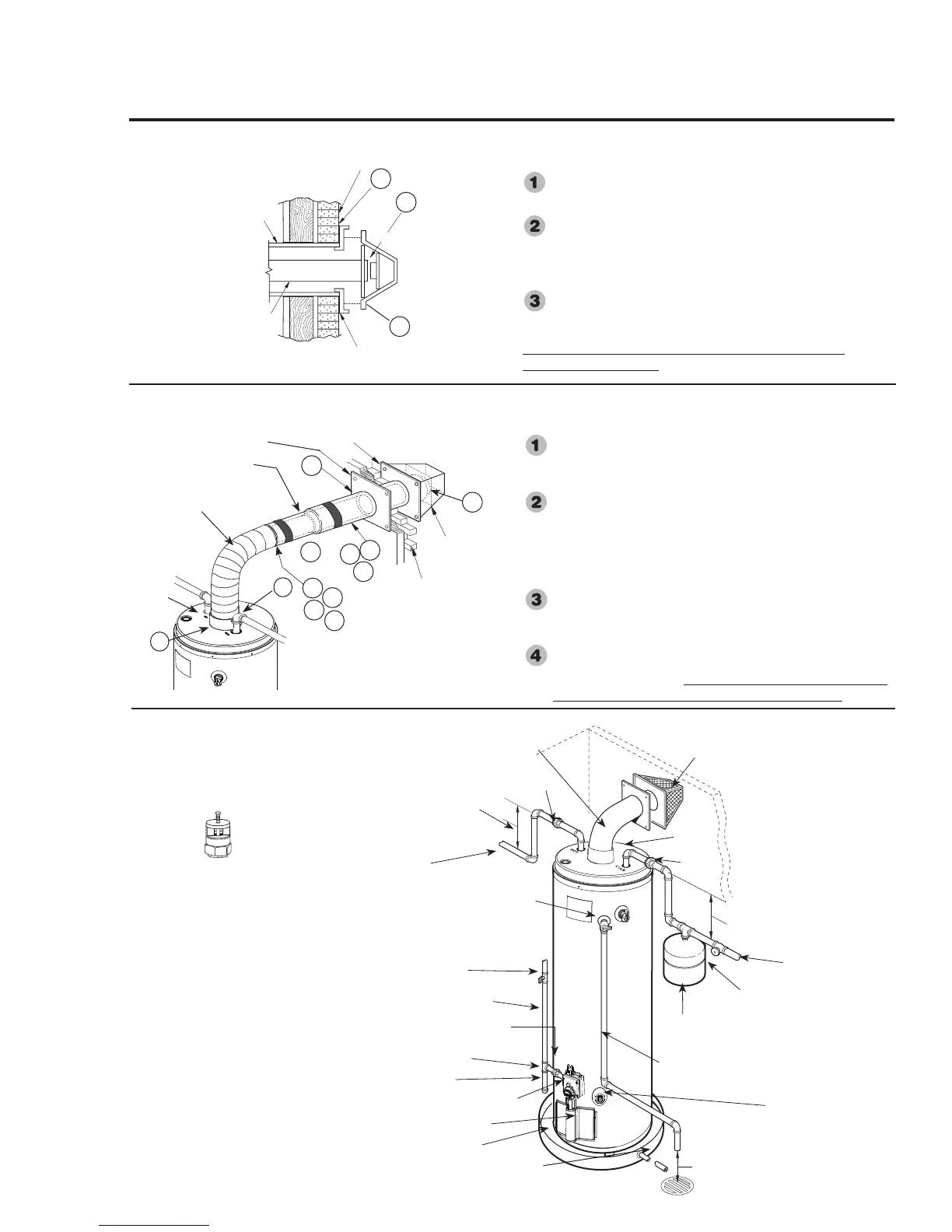
Installing the water heater.
Typical Installation
Heat Trap
6" Min (15.2 cm).
Vent Terminal Cap
(Outside)
Heat Trap
6" Min. (15.2 cm)
Hot Water
Outlet to
Fixtures
To Cold Water Supply
Temperature
and Pressure
Relief Valve
Relief Valve Discharge Line
to Suitable Open Drain
Expansion Tank
(if required)
Manual Gas Shut-Off
Shut-Off Valve
To Gas Supply
Ground Joint Union
Gas Control (Thermostat)
Jacket Door
Drain Valve
Auxiliary Catch Pan
Air Gap - 6" (15.2 cm)
Cap
Air Tube
Sediment Trap
Union
Anode Rod (Located under top pan) Not
accessible. Refer to Protection Plus Kit for
additional protection.
12
Catch Pan Pipe to suitable drain.
J3
J1
J2
L5
L1
K
*
Screw Anchors
Wall
Vent Terminal Base
3" Tube
(7.6 cm)
6" Tube
(15.2 cm)
Seal with Silicone Sealant
Vent Terminal Base (Outside)
Finishing Collar (Inside)
6
” (15.2 cm)
90° Elbow
(Aluminum)
Outside Wall
Vent Terminal
Cap (Outside)
✚✚✚
L2
L3
L2
L3
✚
✚
Sheet Metal Screws
▲Seal with Silicone Band
Securing Vent Cap / Base Assembly to
the Exterior Wall
Next place the 3” (7.6 cm) main tube fully onto the collar
of the vent cap. Then seat the cap against the base. (J1)
Secure the vent cap/base assembly to the exterior wall
with four screw anchors appropriate for the type of wall
construction. The 6” (15.2 cm) tube should be essentially
level. However, a small amount of upward pitch will not
affect operation. (J2)
Caulk the junctions of the vent terminal base and the
exterior wall with silicone sealant (Not Supplied). (J3)
An improper seal can cause product performance and
nuisance pilot outages.
Final Assembly and Sealing of the Vent
System
Position and fasten the finishing collar, previously
installed on the 6” (15.2 cm) elbow, against the wall to
close the opening around the tube. (K)
Make certain the 6” (15.2 cm) inner sliding air tube has
been fully engaged onto the 6" (15.2 cm) elbow.(L1)
Drill two 1/8” inch holes (180° apart) in the junction of
the two joints in the 6" (15.2 cm) tube. (L2)
Fasten with four #8 sheet metal screws supplied. (L3)
Using a flat head screw driver inserted through the holes
in the vent cap, roll the silicone band over the seam to
seal. (L4)
Seal all the 6” (15.2 cm) tube joints with the silicone
bands provided (L5). Seal the elbow joint to the plenum
using silicone sealant. Again, an improper seal can cause
product performance and nuisance pilot outages. (M)
NOTICE: The National
Fuel Gas Code (NFGC)
mandates a manual gas
shut-off valve: See (NFGC)
for complete instructions.
Local codes or plumbing
authority requirements may
vary from the instructions
or diagrams provided and
take precedent over these
instructions.
V a cuum Relief V a lve
(Not Supplied)
If required, install per local codes
and valve manufacturer’s
instructions.
6" Inner Sliding Tube
Top of
Plenum
✱Seal with Silicone Sealant
✱
L4
✱
▲
Union
▲
 Loading...