16
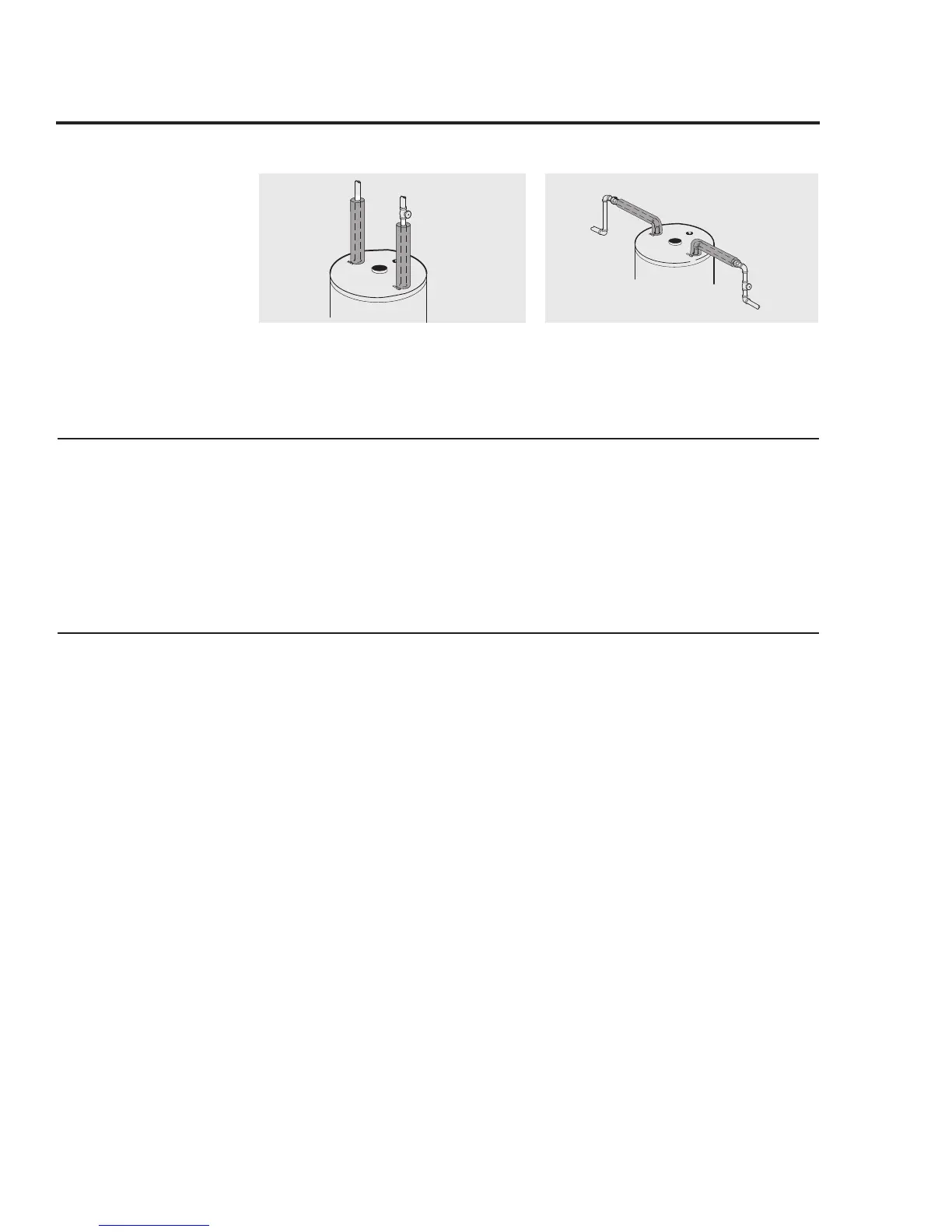
For increased energy efficiency, some
water heaters have been supplied with
two 24” (60.9 cm) sections of pipe
insulation. Please install the insulation,
according to the illustrations above, that
best meets your requirements.
DO
❑ DO check inlet gas pressure to ensure
that it is within the range specified on the
rating plate.
❑ DO provide adequate air for combustion
and ventilation as discussed in the Use and
Care Manual and the National Fuel Gas
Code.
❑ DO maintain proper clearances to
combustibles as specified on the instruction/
warning label.
❑ DO ensure that the venting system
complies with the guidelines found in the
Use and Care Manual and National Fuel Gas
Code.
❑ DO contact a qualified service technician
if the pilot or main burner will not stay lit.
DON’T
❑ DON’T block or restrict the vent
terminal.
❑ DON’T remove the Burner Access
Door unless absolutely necessary. This
should only be done by a qualified service
technician. A new burner access door gasket
must be installed on any burner access door
that has been removed.
❑ DON’T install this water heater where
standing water may occur. The base of the
water heater is meant to be mounted on a dry
surface.
❑ DON’T operate the water heater if the
sight glass or burner access door grommet is
damaged or broken.
Typical vertical piping arrangement
Typical horizontal piping arrangement
During Installation of this water heater...........
Heat Trap
Hot and Cold Pipe Insulation Installation
For increased energy efficiency, some
water heaters have been supplied with
factory installed 3/4” NPT heat traps in
the hot outlet line and cold water inlet
line.
NOTICE: Do not apply heat to the
HOT or COLD water connections. If
sweat connections are used, sweat
tubing to adapter before fitting adapter
to the water connections on heater. Any
heat applied to the water supply fittings
will permanently damage the dip tube,
nipples, and/or heat traps.
Installing the water heater.
 Loading...