33
A, B, C, D
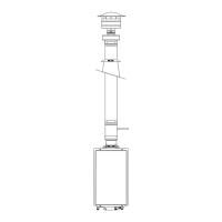
Vent Pipe
Through Roof
The following chart with diagrams details the minimum dimensional information needed to determine the proper location
of the vertical vent terminal for direct-vent indoor tankless water heaters:
Location
U�S� Installation
Requirements
1
Canadian Installation
Requirements
2
A = Minimum clearance above the roof level� 12 in� (30�5 cm) above roof level� 18 in� (45�7 cm) above roof level�
B = Minimum clearance above anticipated snow level� 12 in� (30�5 cm) above
anticipated snow level�
12 in� (30�5 cm) above anticipated snow
level�
C = Maximum clearance above roof level (without ad-
ditional vent support)�
24 in� (61 cm) above roof level� 24 in� (61 cm) above roof level�
D = Maximum clearance above anticipated snow level
(requires additional vent support)�
24 in� (61 cm) above anticipated snow
level�
24 in� (61 cm) above anticipated snow
level�
E = Required vent clearance from any gable, dormer, or
other roof structure with building access (i�e�, vent,
window)�
4 ft� (1�2 m)� 4 ft� (1�2 m)�
F = Required vent clearance from any forced air inlet,
including dryer and furnace air inlets�
10 ft� (3 m) 6 ft� (1�8 m)
1 In accordance with current ANSI Z223�1/NFPA 54 National Fuel Gas Code�
2 In accordance with current CAN/CSA B149�1 Installation Codes�
NOTICE:
Only manufacturer-approved termination and parts
should be used during installation.
Vertical Vent Terminal Location
Venting for Direct-Vent Water Heater
INSTALLATION INSTRUCTIONS
Venting
 Loading...