18
INSTALLATION INSTRUCTIONS
General
NOTICE:
The National Fuel Gas Code (NFGC) and CAN/CSA B149.1 mandate a manual gas shut-off valve.
See NFGC/B149.1 for complete instructions. Local codes or plumbing authority requirements may vary from the instructions or
diagrams provided and take precedence over these instructions.
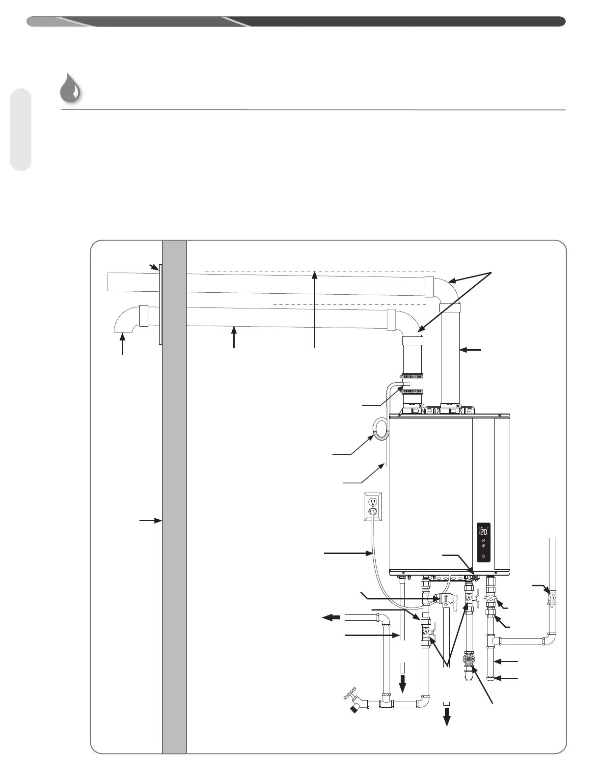
Typical Installation of Direct-Vent Water Heater
Water Heater Installation (cont.)
To
Suitable
Drain
To
Suitable
Drain
To Hot Water
Faucet(s)
Condensate
Pipe*
Union
Relief
Valve
Sediment
Trap
Water
Filter
Manual Gas
Supply Line
Shut-Off Valve
Manual Gas
Shut-Off
Valve
Union
Cap
Cold Water
Supply Shut-Off
Valve
Service
Valve
(supplied)
with some
models)
Power Supply
Cord
Outside
Wall
Wall Plate
(Recommended)
90°
Elbow
Air
Intake
Pipe
Upward Slope to
outside termination
Exhaust Vent Pipe
90°Elbow
Drain
Valve
Condensate Collector
Condensate Trap
To Drain: Dispose of condensate
in accordance to local codes.
 Loading...