RHEONIK Messgeräte GmbH REV. I, Apr. 2004
.
Operation Manual RHE 07, 08, 11
Page
7
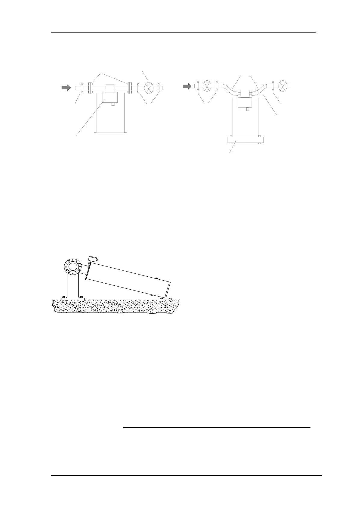
Flow
pipe support
pipe support
shut off valve
terminal box
process
connecton
sensor support
flexible hoses
pipe support
not recommended
for high pressure
as flexible hose
becomes stiff and
puts changing forces
onto the sensor
pipe support
The
sensor must be installed in a position with process connection on the upper side in order to
measure fluids (see sketch) and correspondingly in upside down position for gases (process connec-
tion on bottom and housing on top). The sensor must be completely filled with the medium. At the
same time gas bubbles must be completely removed from the device before the start of operations.
This can be achieved via appropriate flushing for a few minutes with a high throughput for example.
In the case of measuring minimal amounts of fluids (5 – 30 %), the sensor RHM 30, 40, 60, 80, 100,
and 160 can be installed in a nearly horisontal position (parallel to the floor).
For this mounting position, the housing flanges can
be used to secure it. In every instance, the sensor
and the piping must be secured in front of and
behind the sensor. It is preferable to use stiff
piping systems. Avoid extreme reducers, because
these can cause cavities within the measuring
tubes. Reducers should be installed several metres
from the measuring device when required.
In the case of the sensor sizes RHM 30 to 160 with parallel pipe loops, straight lengths of pipe are
foreseen if the medium is fed in from a very different axis than the one allowed by the pipe curve of
the sensor. We recommend a straight pipe with a length 3 – 5 times that of the pipe diameter for the
outflow and 5 – 10 times that of the pipe diameter for the inflow for the above mentioned sensor
designs, in order to prevent any significantly large differences in the flow speeds of the two measur-
ing pipes.
No valves or reducers should be installed between the pipe fixings and the sensor.
In the case of these equipment sizes, be sure to remove the transport safety fixtures before putting
into operation and to reseal the openings.
On bigger meters please remove the transportation fixation screws and reseal the housing
before start-up.
 Loading...