Do you have a question about the RHEONIK RHE Series and is the answer not in the manual?
Introduces the installation guide and its purpose.
Covers copyright, disclaimers, and liability limitations.
Lists other documents providing additional information on the transmitter.
Details the guide's content and intended readers.
Instructions for storing the guide and mention of conformity.
Explains the meaning of symbols used throughout the installation guide.
Explains how warnings are structured and the meaning of hazard levels.
Outlines essential safety measures and precautions for operation.
Specifies the necessary qualifications for personnel working with the device.
Lists the environmental conditions for installing and operating the transmitter.
Lists uses that are contrary to the transmitter's intended purpose.
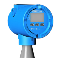
Describes the compact version of the RHE42 Coriolis transmitter.
Describes the remote installation version of the RHE42 Coriolis transmitter.
Details information on the device's type label and defines abbreviations.
Explains the structure and options for the transmitter's model code.
Details protection classes and application areas for explosion protection.
Provides instructions for transporting, storing, and checking the delivered product.
Lists the three available methods for installing the RHE42 Coriolis transmitter.
Step-by-step guide for mounting the transmitter on a wall or plate.
Instructions for installing the transmitter onto a pipe using an accessory.
Details on using connecting cables to link the transmitter and sensor.
Explains connections for power supply, I/O, and signal cables.
Provides diagrams for connecting power, RS485, and Modbus TCP interfaces.
Instructions on how to set the termination switch for RS485 communication.
Guides for connecting Modbus TCP, Foundation Fieldbus, and Profibus interfaces.
Wiring diagrams for connecting non-intrinsically safe analogue outputs.
Describes connection variants for non-intrinsically safe digital outputs.
Explains how to connect digital inputs for switches and drivers.
Details connecting a HART interface to analogue outputs.
Guide for connecting intrinsically safe analogue outputs with certified barriers.
Instructions for connecting intrinsically safe digital outputs and inputs.
Instructions for connecting an intrinsically safe HART interface.
Explains the operation of the transmitter's three keys.
Details password entry for user and service access.
Step-by-step guide for the initial power-on and setup of the transmitter.
Procedure for calibrating the zero point to ensure measurement accuracy.
Instructions on how to reverse the displayed flow direction if needed.
Guide on how to find the IP address for Modbus TCP network connection.
Procedure to configure the RS485 interface for communication.
Steps to configure display units for measured values.
Guide for configuring the settings of analogue outputs.
Instructions on how to configure the various types of digital outputs.
Steps for configuring the settings of digital inputs.
Procedure to test the analogue and digital output signals.
How to reset the mass flow and volume meter readings.
Options for configuring default view, illumination, and error colours.
Adjusting filter settings for measured value stability and response time.
Describes on-site calibration methods against a reference meter.
How to check the transmitter status using Assurance Factor and View.
Steps to display historical zero point values.
How to view and interpret specific error codes and status information.
Details how to read and understand various error codes and their meanings.
Lists soft errors and warnings with causes and solutions.
Provides housing, dimensions, ambient conditions, and interface details.
Details communication options and hazardous area approvals.
Guidelines for returning devices and complying with disposal regulations.
Critical safety guidelines for installing the system in hazardous environments.
Warnings regarding component substitution and opening energized units.
Overview of certifications and electrical safety limits for hazardous areas.
Specifies thermal limits, grounding, and shielding requirements.
Specific installation requirements for CSA certified units.
Explains the structure of the ordering code and its hazardous area relevance.
Lists operating temperature, humidity, altitude, and installation conditions.
Lists standards for ATEX/IECEx hazardous area compliance.
Lists standards for CSA/ETL hazardous area compliance.
Notes on unit service, repair, and voiding Ex-certification.
Presents the official declaration of conformity for the RHE42.
Provides wiring diagrams for non-intrinsically safe connections.
Provides wiring diagrams for intrinsically safe connections.
| Brand | RHEONIK |
|---|---|
| Model | RHE Series |
| Category | Transmitter |
| Language | English |