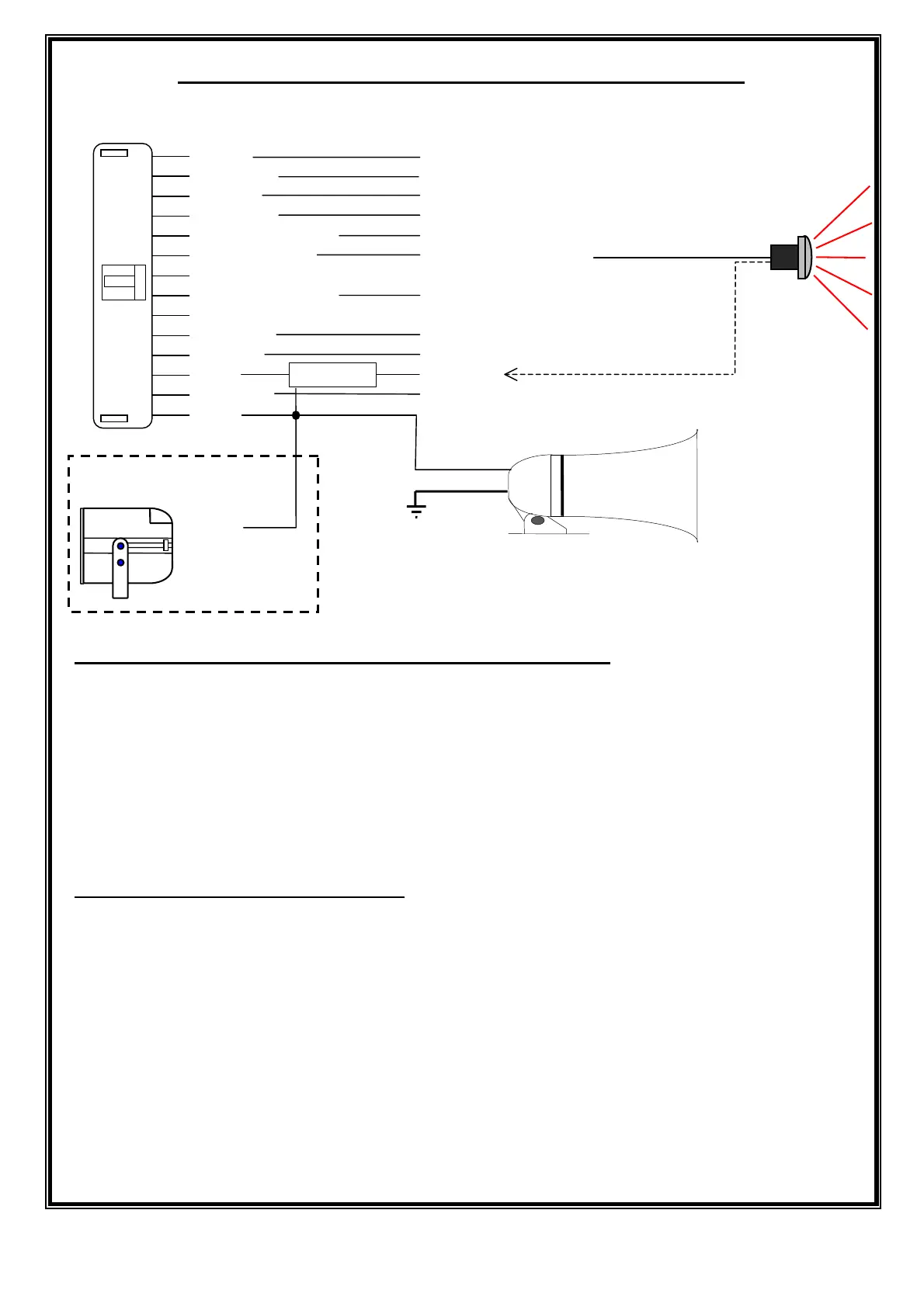
RHINO GL ALARM WIRING DIAGRAM
GREY Ignition Input
ELLOW Negative Trigger Input
WHITE Positive Override Input
ORANGE Negative on Disarm Output
WHITE/YELLOW Negative Pulse Unlock Output
BLUE/GREEN Negative LED Output
Not Used
GREEN/YELLOW Negative Pulse Lock Output
Not Used
BROWN Left or Right Indicator Circuit Output
BLACK Ground / Earth
RED +12VDC
BROWN Left or Right Indicator Circuit Output
PINK Positive Siren Trigger Output
LOCATION GUIDE FOR SYSTEM COMPONENTS
THE SIREN: Mount the siren to the vehicle’s firewall, close to the bonnet.
DO NOT
mount near the exhaust manifold or low down in the engine bay where it may be
exposed to excessive moisture / road grime etc.
THE CONTROL (MAIN) UNIT: Mount under the dash between the steering column &
he centre of the vehicle. Cable tie the unit to a large cable (20mm diameter or larger)
or to a heavy strut.
SECURITY OVERRIDE MODE:
If a customer loses a remote control, or it fails to disarm the alarm system, the
following procedure will disarm the alarm system.
1. Open & close the drivers door. (The siren will sound).
2. Sit inside the vehicle and turn on hidden toggle switch.
3. Within 30 seconds, turn the ignition from off to on 5 times.
4. The system will disarm ( The siren will stop sounding).
5. Contact your Rhino Dealer for further assistance.
INSTALLERS PLEASE NOTE: If power is removed from the alarm system, it will
automatically arm when power is reconnected.
REFER TO WIRING INSTRUCTIONS ON PAGE 4 FOR FULL EXPLANATION
+
-
Standard 12VDC
Single Tone Siren
YELLOW
RED +12
VDC
BLACK EARTH
Optional SBB
Red
Blue
Black
Red
5
 Loading...