WIRING INSTRUCTIONS FOR RHINO GL ALARM
RED
-
Power. Connect to constant +12 volts via the fuse box at the point where the interior light circuit is
powered. Current (voltage) sensing will not work if this procedure is not followed.
BLACK
-
Earth. Connect to a suitable earth on the car body.
BROWN (x2)
-
Indicator Flash Wires.(Positive Output). Connect to the left and right indicator circuits of the vehicle.
GREY
-
Ignition Input. Connect to a +12 volts ignition switched lead, which
does not fall to 0 volt when the engine is
cranked
YELLOW
-
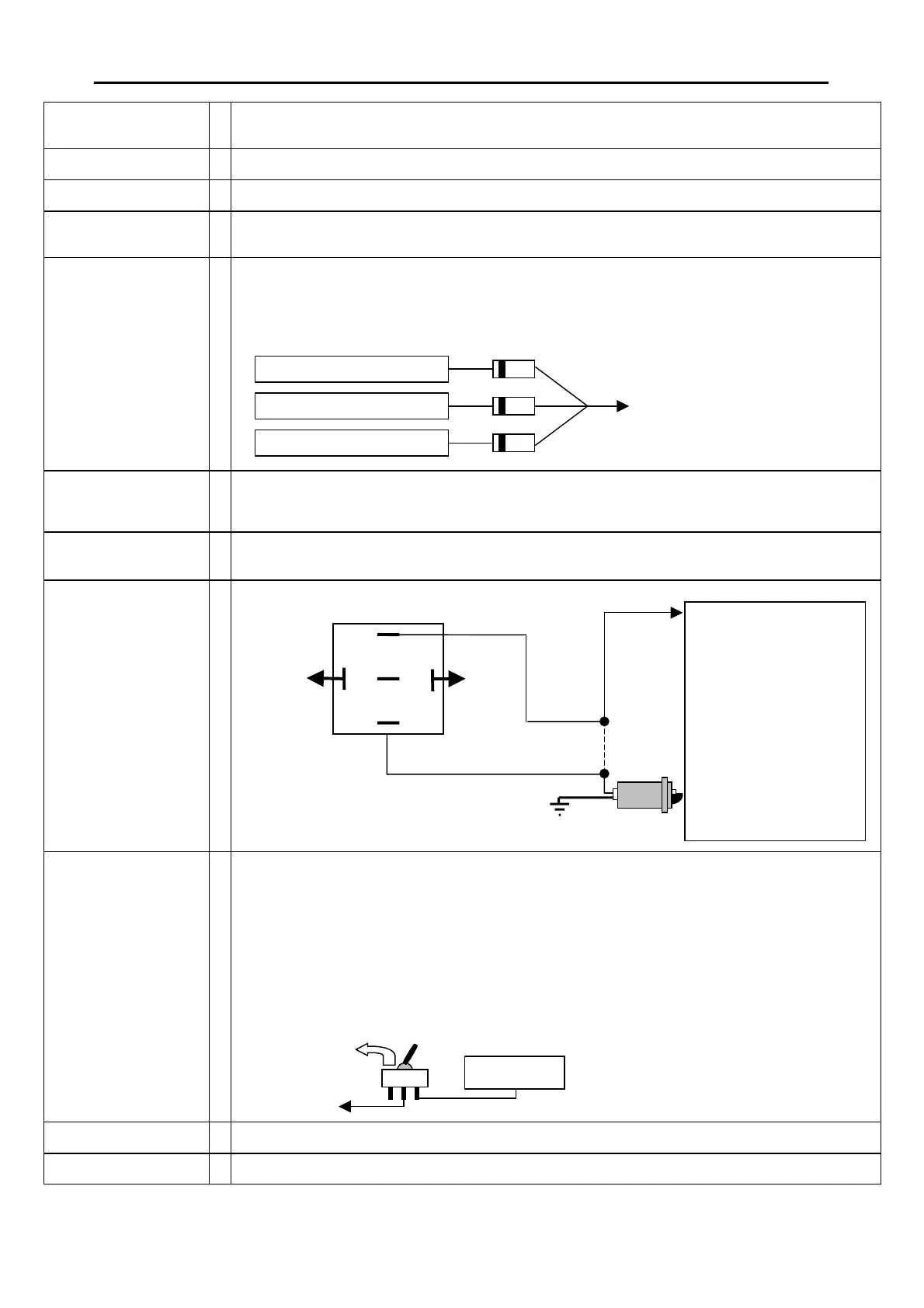
Negative Trigger Input. Connect to existing door switches, bonnet switch provided, or negative trigger wire
from optional car body impact sensor, ultrasonics, or microwave sensor. Please note: only negative switching
doors. If positive door switching - must use relays to reverse to negative - see diagram contained later in this
manual. If you a using more than one trigger device i.e. doors, bonnet, and impact sensor, then the 1 Amp
Diodes supplied must be used on each wire coming from each trigger input i.e.
PINK
-
Positive Siren Trigger (1Amp max rating). This wires switches positive when the alarm is triggered. It also
pulses positive to make the siren beep. Connect to the red wire from the standard 12VDC siren supplied, or
to the yellow positive trigger input wire on the optional SBB Multi-Tone Backup Battery Siren.
BLUE/GREEN
-
Negative LED Output. Connect to the blue wire from the LED supplied. (Connect Red wire from LED to
+12VDC).
ORANGE
-
Negative on Disarm. This wire enables an effective engine immobilisation circuit to be configured with this
alarm. Use 40amp Changeover Relay provided as shown:
WHITE
-
Positive Override Input. This wire needs to be connected to constant +12VDC via the override
toggle switch provided, to allow access to the security override mode:
If a customer loses a remote control, or it fails to disarm the alarm system, the following
procedure will disarm the alarm system.
1. Open & close the drivers door. (The siren will sound).
2. Sit inside the vehicle and turn on hidden toggle switch.
3. Within 30 seconds, turn the ignition from off to on 5 times.
4. The system will disarm ( The siren will stop sounding).
5. Contact your Rhino Dealer for further assistance.
GREEN/YELLOW
-
Negative Pulse Lock Signal. Refer to diagrams contained later in this manual for connection options.
WHITE/YELLOW
-
Negative Pulse Unlock Signal. Refer to diagrams contained later in this manual for connection options.
1 Amp Diodes
Im
act Sensor Ne
. Tri
er Ou
e
ative Door Switch
e
ative Bonnet Switch
Yellow Wire from GL Alarm
85
87a
87
86
30
Ignition
The starter wire is usually
located under the steering
column of the vehicle. This
wire must be +12 Volts only
when the vehicle is being
started. Cut this wire. The
vehicle should not start. Solde
the starter motor side
to
number 30 on the relay. Solde
the other end to number 87 on
the relay. Disable only starte
motor or fuel pump.
Under no circumstances
should you cut the vehicle’s
main ignition system.
Orange
ON
White Wire
+12VDC
4
 Loading...