36
collegamento idraulico
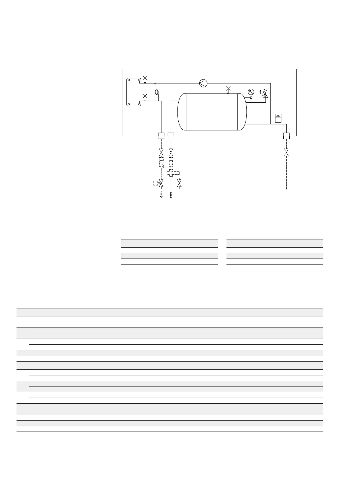
hydraulic connection
∆pw = Prevalenza utile pompa integrata
G=
Portata acqua evaporatore/condensatore
(*) Non disponibile per CWA/ES-CWA/ESX-
CWR/ES 113
∆pw = Built-in pump available pressure
G = Evaporator/condenser water flow
(*) Not available for CWA/ES-CWA/ESX-
CWR/ES 113
Vaso di espansione 14 litri
Expansion tank capacirty: 14 l
Collegamenti idraulici
●● È consigliabile, nei lunghi periodi di
inattività, scaricare l’acqua dall’impianto.
Si può ovviare allo scarico dell’acqua
aggiungendo del glicole etilenico nel circuito
idraulico (vedi utilizzo di soluzioni incongelabili
pag. 26).
●●
Una resistenza a filo caldo avvolta sullo
scambiatore lato acqua evita gli indesiderati
effetti del gelo durante le soste nel
funzionamento invernale.
●●
Si consiglia l’installazione di valvole di sfiato
aria e di valvole di intercettazione che isolino
l’unità dal resto dell’impianto.
Attenzione
●● Montare un filtro a basse perdite di carico
sull’entrata dell’acqua (accessorio KFA).
●● La portata d’acqua attraverso lo
scambiatore non deve scendere al di sotto del
valore corrispondente a un salto termico di
8°C.
Hydraulic connections
●● Discharging the water from the system is
advisable for seasonal stop. Otherwise using a
water/glycol solution is possible (see use of
antifreeze solutions on page 26).
●● A trace electrical heater reduces the freezing
risk during the winter stops, when the trace
electrical heater control accessory (KFC) is ON.
●● It is recommended the installation of air vent
and intercepting valves to insulate the unit from
the system.
Attention
●● Mount a low pressure drop filter at the water
inlet (KFA accessory).
●● The water flow should not decrease below
the value correspondent to a water ∆t of 8°C.
TANK & PUMP - Prevalenza utile elettropompa gruppo ASP
TANK & PUMP - ASP pump available pressure
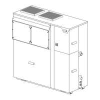
TANK & PUMP
Versione con gruppo di pompaggio e accumulo integrati ASP
Version with built-in water tank ASP
fig. 15
Dati serbatoio di accumulo
Water tank data
CWA/E - CWA/EX - CWR/E CWA/ES - CWA/ESX - CWR/ES
Unità
Contenuto acqua serbatoio di accumulo (litri)
Units
Water tank capacity (litres)
29 - 35 80
42 - 50 - 57 - 70 - 85 - 100 - 113 150
125 - 140 - 153 290
Unità
Contenuto acqua serbatoio di accumulo (litri)
Units
Water tank capacity (litres)
29 80
35 - 42 - 50 - 57 - 70 - 85 - 100 150
113 - 125 - 140 - 153 290
Unità Pompa
G (l/h)
3.450 4.600 5.800 6.300 7.080 7.800 8.500 9.200 10.000 10.600 11.320 12.000 13.000 14.150
Units Pump.
29
P1
∆pw (kPa)
148 127 100 8868---------
P3
∆pw (kPa)
231 209 180 172153---------
35
P1
∆pw (kPa)
- 136 115 104 82 6241-------
P3
∆pw (kPa)
- 214 193 182 165 146125-------
42
P1
∆pw (kPa)
- - 127 118 104 91 75 6241-----
P3
∆pw (kPa)
- - 216 208 193 177 155 14017798----
50 P3
∆pw (kPa)
- - - 200 186 173 159 144 128 114 97 81 - -
57 P3
∆pw (kPa)
----195182169155138124105 91 65 33
Unità Pompa
G (l/h)
8.300 11.000 14.080 16.000 17.100 18.500 20.060 21.000 22.600 24.000 25.100 26.500 27.920 29.500 30.600 34.000 38.000
Units Pump.
70
P5
∆pw (kPa)
170 152 125 10592------------
P7
∆pw (kPa)
293 274 245 223209------------
85
P5
∆pw (kPa)
- 157 134 116 105 907160---------
P7
∆pw (kPa)
- 277 254 235 223 207187174---------
100
P5
∆pw (kPa)
- - 160 126 113 98 80 7050--------
P7
∆pw (kPa)
- - 258 239 227 211 192 180157136-------
113
P 5 (*)
∆pw (kPa)
- - 137 123 114 102 88 79 62 49 37 22 - - - - -
P7
∆pw (kPa)
- - 262 245 235 221 206 196 176 161 147 127 105 - - - -
125 P7
∆pw (kPa)
- - - 248 238 226 210 201 184 167 153 136 117 94 78 - -
140 P7
∆pw (kPa)
----242228212202184168155137116 98 83 34 -
153 P7
∆pw (kPa)
-----23221820919217616314512610485 32 -
 Loading...