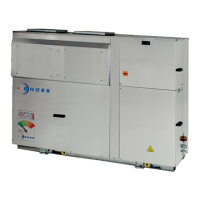
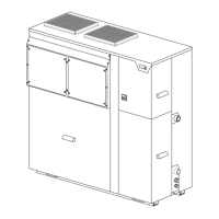
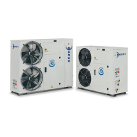
This document describes the TCCEY-THCEY 114-128 series of air and centrifugal-fan-cooled water chillers and heat pumps, designed with hermetic Scroll compressors and R410A ecological refrigerant. The units are intended for use in air conditioning systems or industrial process applications requiring chilled or hot and chilled water, and are not for human consumption.
Function Description
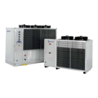
The TCCEY units are self-contained air-cooled water chillers, while the TCCEY T and H units include a storage tank and pump. The THCEY units are self-contained heat pumps with air evaporation/condensation, with THCEY T and H versions also including a storage tank and pump. Both ranges are equipped with centrifugal fans.
The core of the device's functionality is the new AdaptiveFunction Plus adaptive control logic, an exclusive RHOSS patent developed in collaboration with the University of Padua. This advanced logic aims to optimize the chiller's operation based on the system characteristics and actual thermal load. Unlike traditional control systems that typically focus on maintaining a fixed return water temperature, AdaptiveFunction Plus dynamically adjusts the flow water temperature. It achieves this by using:
- Information from both return and flow water temperatures to estimate load conditions through a specific mathematical function.
- A special adaptive algorithm that uses this load estimate to vary the start-up and switch-off thresholds and positions of the compressors. This optimized compressor start-up control ensures maximum precision in the water supplied to the utility, reducing temperature fluctuations around the set-point value.
The system offers two main operating modes: "Economy" for energy efficiency and "Precision" for high temperature accuracy.
- Low consumption chiller: "Economy" Option: This mode is designed to maximize energy efficiency, especially under partial load conditions, which represent most of the operating time. The controller ensures the water flow temperature is as high as possible (in chiller mode) or as low as possible (in heat pump mode), while remaining compatible with thermal loads. This dynamic adjustment prevents energy waste associated with maintaining unnecessarily low or high temperatures, ensuring optimal comfort and significant seasonal energy savings. For instance, the Compact-Y unit with 4 shutter steps provides substantial seasonal electrical energy savings in both summer and winter.
- High precision: "Precision" Option: This mode guarantees high accuracy and reliability for applications requiring a constant water supply temperature and precise humidity control. The unit operates at a fixed set-point, and thanks to advanced water flow temperature control, it can maintain an average fluctuation of approximately ±1.5°C from the set-point value for loads between 50% and 100%, compared to ±3°C with standard return control. This mode is particularly beneficial for process applications, where a storage tank with greater system water content is recommended to ensure high thermal inertia.
A unique feature is the "Virtual Tank" function, which enhances reliability even with low water content in the system (as little as 2 litres/kW in the pipes). This function compensates for the lack of inertia from a physical storage tank by "muffling" the control signal, preventing untimely compressor starts and stops, and reducing average set-point fluctuations. This leads to more stable temperatures and reduced energy consumption.
The unit also includes an "Autotuning" compressor management function. This allows the Compact-Y units to self-adapt to the system by learning its thermal inertia characteristics during initial operation. The function performs preset operating cycles, processes water temperature data, and estimates the system's physical characteristics to determine optimal control parameters. This autotuning remains active, continuously adapting control parameters to changes in the hydraulic circuit and water content.
Important Technical Specifications
The TCCEY-THCEY 114-128 series includes models with nominal cooling capacities ranging from 13.4 kW to 26.7 kW and nominal heating capacities from 13.6 kW to 29.1 kW. Each unit is equipped with a single Scroll compressor.
Refrigerant and Oil:
- The units use R410A ecological refrigerant, a mixture of 50% Difluoromethane (HFC 32) and 50% Pentafluoroetano (HFC 125).
- HFC 32 has a GWP (Global Warming Potential) of 550 over 100 years.
- HFC 125 has a GWP of 3400 over 100 years.
- The R410A mixture has an ODP (Ozone Depletion Potential) of 0, meaning it does not deplete the ozone layer.
- The lubricant used is polyester oil.
- Refrigerant charge and oil charge values are specified on the serial number plate.
Electrical Data:
- Power supply: 400V-3ph+N-50Hz.
- Auxiliary power supply: 230V-1ph-50Hz.
- Total absorbed power (Summer mode) ranges from 5.2 kW to 10.9 kW.
- Total absorbed power (Winter mode) ranges from 5.2 kW to 10.2 kW.
- Nominal current ranges from 15.8 A to 34.5 A, with maximum current up to 38.4 A.
- Starting current ranges from 74 A to 115 A (or 54 A to 86 A with SFS).
Hydraulic Connections:
- Water inlet/outlet connections are 1 1/2"G (male).
- Condensate drain (for THCEY only) is 30 mm.
- Accumulation drain is 1/2"G (female) for T and H versions.
- Minimum water pressure: 0.5 bar.
- Maximum water pressure: 3 bar.
- Heat exchanger nominal flow ranges from 2300 I/h to 4600 I/h.
- Heat exchanger water content ranges from 1.33 l to 2.4 l.
- Heat exchanger nominal pressure drops range from 16 kPa to 22 kPa.
- Circulator available head pressure (for T and H versions) ranges from 44 kPa to 179 kPa.
- Tank water content (for T and H versions) ranges from 55 l to 80 l.
Operating Limits:
- Cooling cycle: Air intake temperature 20°C to 42°C, output water temperature at 7°C. The unit should not operate with output water temperature above 18°C.
- Heating cycle (for THCEY): Air intake temperature -5°C to 20°C, output water temperature 30°C to 55°C. Maximum water inlet temperature 48°C.
- Freezing protection: The control board protects the heat exchanger from freezing by tripping an antifreeze alarm if the probe temperature reaches the set point. Ethylene glycol can be mixed with water for frost protection, but this alters unit performance.
Sound Levels:
- Sound pressure level: 54 dB(A) to 61 dB(A) (measured at 5m from the unit, with directional factor 2 and ducted fan flow).
- Sound power: 77 dB(A) to 84 dB(A).
Usage Features
The units are designed for indoor installation. Proper installation requires adherence to minimum technical spaces, correct leveling, and placement on a supporting surface capable of sustaining its weight. It is crucial to prevent mixing of drawn air with expelled air, recommending ducting the fan discharge air to the outside. The supply air ducting must maintain a constant section equal to the fan discharge section. Anti-vibration fittings (KRAM kit for outlet, KRAS kit for intake) are available to prevent vibration transmission.
Controls:
The units are controlled via a master switch, circuit breaker, and a user interface panel.
- General Switch: A manually controlled "b" type mains power supply disconnection device (ref. EN 60204-1§5.3.2) with a minimum contact opening distance of 3 mm.
- Circuit Breaker Switches: Automatic compressor protection switch, fan protection fuses (for sizes 114-126), and a fan protection circuit breaker switch (for size 128).
- Remote Management: The unit supports remote ON/OFF control (SCR selector), summer/winter enabling (SEI selector for THCEY), and general lockout light (LBG). Connections are made via screened cables (0.5 mm² twisted pair) with a maximum distance of 30 m. An optional remote keyboard (KTR) and clock card (KSC) are available for advanced remote control and scheduling.
Start-up Procedure:
Before start-up, verify electrical supply characteristics, ensure tight electrical terminals, and confirm correct hydraulic connections according to arrows. The air-side heat exchanger must be clean and well-ventilated. The unit is started by pressing the ON/OFF or RESET-DOWN key on the control keyboard. The MODE-UP key selects the operating mode (chiller or heat-pump). The pump starts first, followed by the fan and then the compressor after safety time intervals.
Maintenance Features
Maintenance operations, even for inspection purposes, must be carried out by skilled technicians qualified in air conditioning and refrigeration. Always isolate the unit from the mains using the master switch before any maintenance, ensuring it is locked in the zero position.
Scheduled Checks (Every 6 months):
- Check gas charge and for gas leaks.
- Verify unit power consumption.
- Check water differential pressure switch operation.
- Bleed air from the hydraulic system.
- Inspect contactors on the electric panel.
End of Season Maintenance (with unit switched off):
- Check cleanliness of the air-side heat exchanger.
- Drain the water system.
- Inspect and tighten electrical contacts and terminals.
Routine Maintenance:
- Refrigerant Circuit: Check refrigerant charge and for leaks using a leak detector. Ensure the air-side heat exchanger is clean by removing foreign bodies, vacuuming dust, and gently washing with water.
- Hydraulic Circuit: Check the water differential pressure switch operation. Bleed air from the chilled water system using the bleed valve. Drain the water system for T units via the storage tank drain cock and pump cap, and for units without storage via the cock under the heat exchanger outlet pipe. If antifreeze is used, it must be collected for recycling.
- Electrical Circuit: Check unit power consumption with a clip-on meter and compare it to technical data. Inspect electrical contacts and terminals for tightness with the unit disconnected from the power supply.
Special Maintenance:
- Component Replacement: Before replacing components, switch off the unit and drain refrigerant from both high and low-pressure sides to prevent hazards from pressurized refrigerant and oil.
- Restoring Refrigerant Load: Rapidly filling only the suction side can damage the compressor. It is recommended to fill both high and low-pressure sides simultaneously. R410A refrigerant must be topped up in liquid phase from the cylinder to maintain its composition.
Dismantling and Disposal:
The unit must be dismantled by an authorized firm for scrap machinery/products. Materials are largely recyclable.
- Compressor oil must be removed and delivered to an authorized waste oil collection facility.
- Antifreeze, if present, must be collected and recycled.
- Refrigerant fluid must not be discharged into the atmosphere; it must be recovered using homologated devices and delivered to an authorized collection company.
- Filter-drier and electronic components (electrolytic condensers) are special waste and must be delivered to an authorized body.
- Insulation materials (polyurethane rubber, polyethylene mesh, expanded polyurethane, polystyrene packaging, sound-absorbent sponge) must be removed and processed as urban refuse.
The product should not be disposed of with household waste and must be disposed of according to local laws and regulations. RHOSS S.p.A. can collect used equipment free of charge. Separate collection and recycling help conserve natural resources and protect human health and the environment.