Do you have a question about the Rhymebus RM5G Series and is the answer not in the manual?
Explains the meaning of DANGER and CAUTION symbols for hazardous situations.
Lists key features and benefits of the RM5G series inverter.
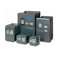
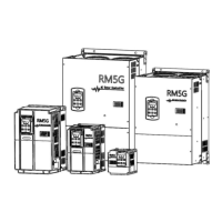
Details on checking the inverter's appearance, specifications, and accessories upon receipt.
Provides detailed technical specifications for the RM5G series, including power and frequency ratings.
Outlines common specifications across different models, covering interface, control, and environmental aspects.
Essential components and considerations for the basic setup of the inverter system.
Guidelines for the operational environment, including power source and location for heat dissipation.
Detailed explanation of inverter terminals and comprehensive wiring diagrams for different HP ranges.
Description and functions of the KP-201C digital keypad for inverter operation.
Description and functions of the KP-202C analog keypad for inverter operation.
Explains the different modes and display settings of the KP-201C digital keypad.
Details functions and settings of the KP-202C analog keypad and its RSW switches.
Describes function codes related to keypad operations, version, and start/stop commands.
Details function codes for setting multiple speed levels and their associated acceleration/deceleration times.
Outlines function codes for overload, stall prevention, and other motor protection settings.
Covers function codes related to DC braking, including current, time intervals, and frequency settings.
Details function codes for configuring inverter behavior after a power interruption, including restart and shutdown.
Explains function codes for customizing the analog keypad's ADJ, DIP, and potentiometer settings.
Provides step-by-step instructions for operating the inverter, including safety warnings and inverter sizing.
Details inverter protections, fault displays, and troubleshooting steps for common issues.
Information on dynamic brake units, resistors, and their specifications and references.
Guidelines for selecting appropriate standard and special motors for use with the inverter.
Recommendations for selecting and installing AC reactors based on power source and harmonic considerations.
Details the types, dimensions, and wiring of remote controllers for inverter operation.
Information on the DM-501 remote indicator, its display capabilities, and connection.
Wiring diagrams and recommendations for connecting braking resistors to the inverter for protection.
Wiring diagrams and recommendations for connecting dynamic braking units to the inverter.
A summary table of function codes and their factory default settings for quick reference.
Lists and explains various error trip and warning displays shown on the inverter keypad.
| Brand | Rhymebus |
|---|---|
| Model | RM5G Series |
| Category | Controller |
| Language | English |