Do you have a question about the Rhymebus RM6 Series and is the answer not in the manual?
Safety warnings during operation, including cover removal and restart behavior.
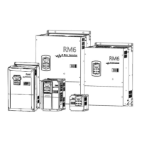
Key features of the RM6 series drive, including control modes and protections.
Steps to verify the product upon receipt, checking appearance and nameplate.
General specifications applicable to all RM6 series drives.
Details on control methods, frequency settings, and other operational features.
Details on input/output terminals, display options, and protection mechanisms.
General guidelines and precautions for installing the drive.
Recommendations for drive placement to ensure adequate clearance and heat dissipation.
Diagrams illustrating correct and incorrect drive mounting for internal cooling.
Diagrams showing correct and incorrect drive mounting for external cooling.
Detailed description of terminals and the wiring diagram for single-phase drives.
Wiring diagram for RM6 series drives, showing AC and DC reactor connections and jumper settings.
Description of main circuit terminals for power source, motor, braking, and grounding.
Detailed description of each main circuit terminal and its function.
Wiring diagrams and specifications for high-horsepower drives, including DBU and reactor connections.
Description of control power and input terminals, including multi-function inputs.
Details on control circuit terminals, including analog inputs/outputs and common terminals.
Control terminals and switches specifically for multi-pump applications.
Diagram and description of the control board for higher capacity RM6 series models.
Wiring cautions and specifications related to switching frequency and cable length.
Recommended wire sizes and MCCB ratings for 400V series RM6 models.
Wiring diagrams and parameter settings for single and multi-pump applications.
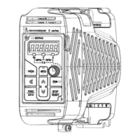
Overview of the keypad's functions and indicators.
Explanation of the symbols and their meanings on the keypad display.
Description of each key on the KP-207 keypad and its function.
How to operate the keypad and switch between monitor, function, and parameter modes.
Step-by-step guide to operating the keypad, including entering different modes and handling faults.
Explanation of the seven available displays in monitor mode and how to switch them.
Steps for navigating and selecting functions in setting mode.
Steps for entering parameter setting mode and modifying values.
Procedure for starting and stopping the drive using the keypad.
Functions for copying parameters, restoring defaults, and saving/restoring settings.
Steps for writing parameters from the keypad to the drive.
How to restore the drive to its default values for different operating conditions.
Procedures for saving and restoring the current drive settings.
Parameters related to pressure transmitter feedback and pump operation.
Details on parameters for pressure transmitter settings and feedback.
Enabling trip detection for feedback signal errors.
Configuration for sequential and parallel control of multiple pumps.
Parameters and diagrams for sequential pump operation.
Setting the mode for sequential pump operation.
Setting the operating time for sequential pump control.
Setting delay time to stabilize pressure during pump switching.
Parameters and descriptions for parallel pump control modes.
Selecting the mode for parallel pump control (E-mode, F-mode, M-mode).
Assigning unique numbers to drives for parallel control.
Setting the detection time for parallel pump startup.
Setting the detection level for parallel pump startup.
Setting the cut-off frequency to stop parallel pump operation.
Setting the cut-off time to stop parallel pump operation.
Setting the number of standby drives for system protection.
Detailed configurations for multi-function input and output terminals.
Configuring functions for multi-function output terminals Ta2, Tc2.
Settings for constant pressure and ON/OFF control modes.
Parameters and diagrams for constant pressure control mode.
Parameters and diagrams for ON/OFF control mode.
Setting the dead band for ON/OFF mode pressure control.
Parameters and descriptions related to PID control functions.
Block diagram illustrating the PID control loop and its parameters.
Functions and parameters for pump protection against water shortage.
Protection against over pressure in water pipes and systems.
Procedures for handling error trips and auto-restart.
Functions and parameters related to drive overheating and fan control.
Step-by-step guide for operating the drive after installation.
List of drive error messages, their causes, and troubleshooting steps.
Error messages specific to constant pressure control mode.
Danger warning for faulty dynamic brake units and thermal protection.
Wiring diagrams for external braking resistor and thermal switch protection.
Wiring diagrams for external dynamic brake units and thermal switches.
Wiring diagram for controlling magnet contactor with a thermal switch and DBU.
Default values for pressure transmitter setting.
Default values for maximum operational pressure.
Default values for pump sequential control mode.
Default values for pump parallel control mode.
Default values for multi-function input terminal X1.
Default values for multi-function input terminal X2.
Default values for multi-function input terminal X3.
Default values for multi-function input terminal X4.
Default values for multi-function output terminal Y1.
Default values for multi-function output terminal Y2.
Default values for multi-function output terminals Ta1,Tb1.
Default values for pressure boost for water usage detection.
Default values for time interval of pressure boost for water usage detection.
Default values for ON/OFF mode starting rate setting.
Default values for PID compensation gain.
Default values for PID control mode selection.
Default values for proportional gain (P).
Default values for integration time (I).
Default values for derivative time (D).
Default values for acceleration time of pressure boost.
Default values for water shortage trip recovery.
Default values for water shortage detection by pressure level.
Default values for water shortage detection by current level.
Default values for time of water shortage detection.
Default values for drive shutdown time for water shortage.
Default values for over pressure disposal.
Default values for over pressure level.
Default values for over pressure detection time.
Memo for Pressure Transmitter Setting.
Memo for Maximum Operational Pressure.
Memo for PID Compensation Gain.
Memo for PID Control Mode Selection.
Memo for Proportional Gain(P).
Memo for Integration Time(I).
Memo for Derivative Time(D).
Memo for Water Shortage Trip Recovery.
Memo for Water Shortage Detection by Pressure Level.
Memo for Water Shortage Detection by Current Level.
Memo for Time of Water Shortage Detection.
Memo for Drive Shutdown Time for Water Shortage.
Display codes for drive error trips, including EEPROM, A/D converter, fuse, short circuit, voltage, current, grounding, over voltage, and overheating errors.
Error messages specific to constant pressure control mode: PID feedback, over pressure, and water shortage.
Display codes for drive warnings: power source under voltage, output interruption, coast to stop, dynamic brake, software fault, and over pressure.