EasyManua.ls Logo

RIB J - User Manual

RIB J
28 pages
Go to English
Print Icon
To Next Page IconTo Next Page
Loading...
J fw04
ITALIANO pag. 04 / FRANÇAIS pag. 10 / ENGLISH page 16 / ESPAÑOL pag. 22
Con AUTOTEST coste di sicurezza come richiesto dalla norma EN12453
e con funzionamento a uomo presente se le fotocellule o le coste sono
guaste. Conforme alle normative in vigore.
ATTENZIONE: NON COLLEGARE OROLOGI.
Per il collegamento di un orologio richiedere la versione del quadro di
comando J con firmware 02.
Assicurarsi che eventuali altri tipi di accessori di comando (per esempio
sensori magnetici) siano programmati nella modalità IMPULSIVA, altrimenti
attiverebbero la movimentazione della serranda senza sicurezze attive.
Avec AUTOTEST barre palpeuse de sécuritécomme requis par la norme
EN12453 et travail avec homme present, dans le cas de panne de
sécurité. Conforme aux Normes en vigueur.
ATTENTION: NE PAS CONNECTER HORLOGES.
Pour utiliser la FUNCTION HORLOGE demander J avec firmware 02.
Faire attention que des autres accessoires pour le commande (p.e. senseurs
magnétique) sont programmée avec modalité IMPULSIVE, ou contraire, le
mouvement est sans sécurité.
With safety strip AUTOTEST as required by EN12453 and functioning in
dead man mode when the safety devices are failing.
According to current European Norms.
ATTENTION: DO NOT CONNECT TIMERS.
If you want the Clock Function must request J with firmware 02.
Make sure that any other type of command accessories (e.g. mass
detectors) used on the installation are set in the IMPULSIVE mode,
otherwise, the rolling shutter will be operated even without the protection
of the safety devices.
Con AUTOTEST costas de seguridad como requerido por la norma
EN12453 y funcionamiento a hombre presente en caso de averías con los
accesorios de seguridad. En conformidad a las Normas en vigor.
ADVERTENCIA: NO CONECTE TEMPORIZADORES.
Para utilizar la función de reloje solicitar J con firmware 02.
Asegúrese de que cualquier otro accesorios de comando que se instalan
(por ejemplo, sensores magnéticos) están programados en el modo de
IMPULSO, de lo contrario pueden activar el movimiento de la puerta sin
tener activos los elementos de seguridad.
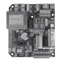
code ABJ7081 J 230V 50-60 Hz 1P
code ABJ7081W J Wi-Fi
code ABJ7082 J 120V 60 Hz 1P
code AC07081 J 230V solo scheda, seule carte, only pc board, solo tarjeta de control
code BA03225 J 120V solo scheda, seule carte, only pc board, solo tarjeta de control
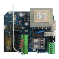
code ABJ7080 J-CRX 230V 50-60Hz 1P
code ABJ7079 J-CRX 120V 60Hz 1P
code AC07080 J-CRX 230V solo scheda, seule carte, only pc board, solo tarjeta de control
code BA03224 J-CRX 120V solo scheda, seule carte, only pc board, solo tarjeta de control

Questions and Answers

  • J
    Jay MartinezAug 5, 2025
    What to do if the RIB J shutter doesn't open or close with K and RADIO buttons?
    • T
      Taylor VaughnAug 5, 2025
      If your RIB Control Panel shutter isn't responding to the K or RADIO buttons, it could be due to a faulty safety edge contact or faulty photocells contact with DIP 4 OFF. You should fix or replace the relative contact to resolve this issue.
  • B
    Brett WilliamsAug 11, 2025
    Why does my RIB J Control Panel shutter open but not close after the set time?
    • H
      hsmithAug 11, 2025
      If your RIB Control Panel shutter opens but doesn't close after the set time, ensure DIP 3 is set to ON and the K BUTTON is always inserted in automatic functioning mode (DIP 6 OFF). You may need to replace the button or switch of the selector switch. Also, check the connections between the electronic board and the edge feeder, in case of a failed edge self-test. If you're not using a feeder for edges, DIP 10 must be in the OFF position.
  • H
    Henry MooreAug 16, 2025
    How to fix a RIB J Control Panel shutter that doesn't move when activating the K button?
    • T
      Tom KeyAug 16, 2025
      If the RIB Control Panel shutter doesn't move when you activate the K button, it could be because Impulse K is always inserted. Check and replace any faulty buttons or micro-switches of the selector switch.
  • K
    kevin71Aug 23, 2025
    Why is my RIB J motor weak and moving slowly?
    • P
      paynebenjaminAug 23, 2025
      If the motor of your RIB Control Panel opens and closes, but lacks strength and moves slowly, check the trimmer TORQUE adjustment.
  • J
    Jesse JonesAug 28, 2025
    What to do if all the LEDs are off on my RIB J?
    • S
      Sheila HaneyAug 28, 2025
      If all the LEDs are switched off on your RIB Control Panel after making connections and supplying voltage, check the integrity of fuses F1 and F2. If a fuse is interrupted, replace it with one of the adequate value: F2 = 5A, F1 = 100mA.

Summary

Important Safety Instructions

General Safety Instructions

Emphasizes the critical need to follow all safety instructions for user protection.

Instruction Retention

Instruction to retain the manual for future reference and use.

Installation Safety Guidelines

Detailed guidelines for safe installation of the automation system.

Electric Connections

Connection Points

Details on various connection points for power, motor, radio, and accessories.

Fuse Information

Specifies the types and ratings of fuses used in the system.

Relay and Motor Control

Details on relays for flasher, travel limits, and motor control.

System Settings (DIP Switches)

Configuration options via DIP switches for operation modes and functions.

LED Status Indicators

Explanation of LED signals for programming and operational status.

Motor Rotation Direction Check

Procedure to verify and correct the motor's rotation direction.

Manned Position Operation

How to operate the system using a continuously pressed command.

Time Setting Procedure

Steps for setting the automatic closing pause time.

Radio Code Learning

Procedure for programming radio transmitter codes.

Radio Code Cancellation

Procedure for erasing all programmed radio transmitter codes.

Memory Saturation Signaling

Indicates when the radio code memory is full.

Operating Accessories

Guidelines for connecting and using impulsive command accessories.

Operation Button Functionality

Details on how the main operation button controls the gate.

Clock Function Usage

Information on using the clock function and its safety implications.

Safety Accessories Operation

How safety accessories like photocells and safety strips function.

Photocell Operation

Detailed explanation of photocell functions and DIP4 settings.

Safety Strip Functionality

Description of safety strip operation, alarms, and testing.

Dead Man Mode

Operation mode when safety devices fail, requiring constant button press.

Blinker and Flashing Light Options

Configuration for connecting blinkers or courtesy lights.

Pre-Flashing Function

Setting for the flashing light to activate before motor movement.

Automatic Closing Setting

How to enable and set the pause time for automatic closing.

Power Shut Off Recovery

Procedure for restoring operation after a power interruption.

Technical Data

Specifications including voltage, frequency, power, and dimensions.

Troubleshooting Guide

Troubleshooting Common Issues

Identifies common faults and provides solutions for system problems.

Control and Safety Accessories

Safety Boxes

Description of safety boxes for controlling devices.

Push Button Controls

Details on flat surface mounted push buttons for automation control.

Key Selector Controls

Information on key selectors for automation control.

Photocell Systems

Details on photocells and columns for automation systems.

Spark Blinker and Antenna

Information on spark blinkers and radio antennas for the system.

Radio Transmitter Sun Series

Overview of the SUN series radio transmitters.

Wireless Safety Accessories

No Touch 868 Photocell System

Details on the world's first radio-operated photocell system.

Master No Touch 868 Unit

Description of the master unit for the No Touch 868 photocell.

Lithium Batteries

Information on the AA lithium batteries used in accessories.

RIB J Specifications

General IconGeneral
Relay OutputSPDT
NEMA RatingNEMA 1
Voltage Rating120VAC
Number of Circuits1
Mounting TypeSurface
MountingSurface
Current Rating10 Amp

Related product manuals