EasyManua.ls Logo

RIB K 2007 CRX User Manual

RIB K 2007 CRX
48 pages
Go to English
To Next Page IconTo Next Page
Page #1 background imageLoading...
Page #1 background image
K 2007 fw.07

NUOVA VERSIONE con funzionamento a uomo presente
se le fotocellule o le coste sono guaste. Conforme
alle normative in vigore.

        


     
     

NOUVELLE VERSION avec travail avec homme present,
dans le cas de panne de sécuri.
Conforme aux Normes en vigueur.

      

       
   


NEW VERSION with functioning in dead man mode
when the safety devices are failing.
According to current European Norms.

         

        
         


NEUE VERSION mit arbeit im mannsbeisein im fall
eines ausfalls der Sicherheiten.
In Übereinstimmung mit der aktuellen Normen.

    


    
        

NUEVA VERSIÓN con funcionamiento a hombre
presente en caso de aveas con los accesorios de
seguridad. En conformidad a las Normas en vigor.
    

       
       
        


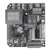
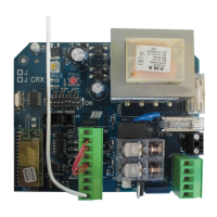
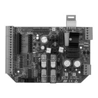
QUADRO ELETTRONICO PER IL COMANDO DI UN MOTORE MONOFASE
COFFRET ÉLECTRONIQUE POUR LE CONTRÔLE D’UN MOTEUR MONOPHASÉ
ELECTRONIC PANEL FOR THE CONTROL OF ONE SINGLE-PHASE MOTOR
ELEKTRONISCHE STEUERUNG FÜR EIN EINPHASIGEN MOTOR
CUADRO ELECTRÓNICO DE MANDO PARA UN MOTOR MONOFÁSICO
Ora con comando pedonale via radio!
Maintenant, avec commande via radio
pour louverture ptonnière!
Now with pedestrian radio control!
Jetzt mit Steuerung der Fußgängeröffnung
über Funk!
¡Ahora con mando de apertura peatonal
a radio!

Questions and Answers:

RIB K 2007 CRX Specifications

General IconGeneral
BrandRIB
ModelK 2007 CRX
CategoryControl Panel
LanguageEnglish

Summary

Safety Instructions for Installation

Specialized Personnel Requirements

Handbook for specialized personnel aware of safety criteria for automated gates.

Installer's User Manual Obligation

Installer must issue a user handbook according to EN 12635.

Risk Analysis and Safety Measures

Installer must perform risk analysis and ensure safety of dangerous points.

External Electrical Component Wiring

Wiring of external components must follow EN 60204-1 and EN 12453.

Manual Control Panel Placement

Place manual controls to avoid dangerous positions and accidental activation.

Control Accessibility and Safety

Keep controls out of children's reach, min 1.5m height, away from mobile parts.

Power Disconnection Procedure

Disconnect power via magnetic-thermal switch before any installation, regulation, or maintenance.

Electrical Safety Device Installation

Install a magnetothermic switch (omnipolar, 3mm contact opening) upstream of the control board.

Cable Type and Standards

Use H05RN-F cable (min 1.5mm²) and follow IEC 364 and local installation standards.

Photocell Positioning and Verification

Photocell beam height max 70cm, distance from door axis max 20cm. Verify function.

Obstacle Detection for High Force Limits

For forces >400N, use active obstacle detection covering full gate height (up to 2.5m).

Electrical Connections and Components

Control Board Wiring Diagram

Diagram illustrating electrical connections for the K 2007 control board.

Connection Terminal Descriptions (J1-J8)

Detailed description of each connection terminal (J1 to J8) on the control board.

Trimmer Functionality (R1, R2)

Explanation of the LOW SPEED (R1) and TORQUE (R2) trimmer functions.

Motor and Relay Operations

Relay and Motor Command Functions

Description of functions for relays (K1, K2, K3) and motor command (Q1).

Low Speed Adjustment

How to adjust the low speed setting using the LOW SPEED trimmer.

Electronic Brake Functionality

Explanation of the electronic brake feature and its settings.

Gradual Start Feature

Description of the gradual start function and its activation.

LED Indicator Functions

Explanation of the meaning of each LED indicator on the control board.

System Settings and Programming

DIP Switch Settings Overview

Configuration options for DIP switches governing system operation.

Motor Type Selection Chart

Chart for selecting the correct motor type using DIP switches.

Checking Motor Rotation Direction

Procedure to check and correct motor rotation direction.

Programming Gate Closing Times

Procedure for programming automatic closing times for the gate.

Programming Pedestrian Opening

Procedure for programming partial pedestrian opening and its auto-closing.

Programming Radio Codes (Complete Opening)

Procedure to program radio transmitter codes for full gate opening.

Deleting All Radio Codes (Complete Opening)

Procedure to delete all stored radio transmitter codes for full opening.

Checking Radio Code Memory Status

How to check if the radio code memory for complete opening is full.

Programming Radio Codes (Pedestrian Opening)

Procedure to program radio transmitter codes for pedestrian opening.

Deleting All Radio Codes (Pedestrian Opening)

Procedure to delete all stored radio transmitter codes for pedestrian opening.

Checking Radio Code Memory Status (Pedestrian)

How to check if the radio code memory for pedestrian opening is full.

Control Accessories and Safety Devices

Accessory Command Modes

Setting of impulsive commands and step-by-step/automatic operation modes.

Pre-Flashing and Buzzer Activation

Functionality of pre-flashing and buzzer activation before gate movement.

Buzzer Operation Modes

Describes intermittent buzzing during normal operation and constant buzzing during alarms.

Gate Open Indicator Functionality

How the LSC terminal indicates gate open status.

Photocell Operation Modes

How photocells function in closing and opening, and with obstacles.

Safety Strip Functionality

How the safety strip operates upon obstacle contact during movement.

Safety Strip Test Function

How to test the safety strip equipment using DIP 10.

Stop Button Integration

How a stop button can be connected to interrupt gate maneuvers.

Dead Man Mode Operation

Operation mode when safety devices fail, requiring manual control.

Flashing Light Connection

Connection details for the flashing light accessory.

Technical Specifications

Environmental and Power Specifications

Technical details on operating temperature, humidity, power supply, and absorption.

Radio Receiver Specifications

Technical specifications for the CRX radio receiver.

Troubleshooting

Initial LED Checks

Checks for LED ignition (DL3, DL4, DL7, DL8) when gate is in intermediate position.

Troubleshooting Common Faults

Solutions for common faults like no LEDs, slow motor, gate not closing, button issues.

Optional Accessories

Radio Transmitters and Receivers

Information on SUN radio transmitters and CODE LEARNIG SYSTEM radio receivers.

Key Selectors and Photocell Systems

Details on key selectors, FIT SLIM photocells, and column pairs.

Safety Strips and Blinker

Information on mechanical safety strips, spark blinkers, and antennas.

Push-Button and Probe Accessories

Details on push-button units and the temperature probe accessory.

Wi-Fi Devices

Master Wi-Fi System

Description of the MASTER Wi-Fi receiver card for wireless system management.

Wireless Accessory Options

Information on NOVA Wi-Fi photocells, BLOCK Wi-Fi key selectors, and VERTIGO Wi-Fi photocells.

Spark and Touch Wi-Fi Accessories

Details on Spark Wi-Fi blinkers and Touch Wi-Fi safety strips.

Red Radio Transmitter for Safety Strips

Information on the RED radio transmitter for mechanical and electrical safety strips.

Maintenance Log and Documentation

Technical Assistance Contact Information

Fields for recording contact details of the technical assistance provider.

Customer Information

Fields for recording customer name, address, and telephone number.

Installed Material Details

Fields for recording details of the installed material.

Maintenance and Service Log Entries

Records of installation, start-up, adjustments, safety checks, repairs, and modifications.

Declaration of Compliance

Compliance with Standards and Directives

Lists relevant European standards and directives the product complies with.

Product Integration and Commissioning Disclaimer

States the product must be integrated into a system and cannot be put into service until the system is compliant.

Related product manuals