Pag. 18 di 36
E
N
G
L
I
S
H
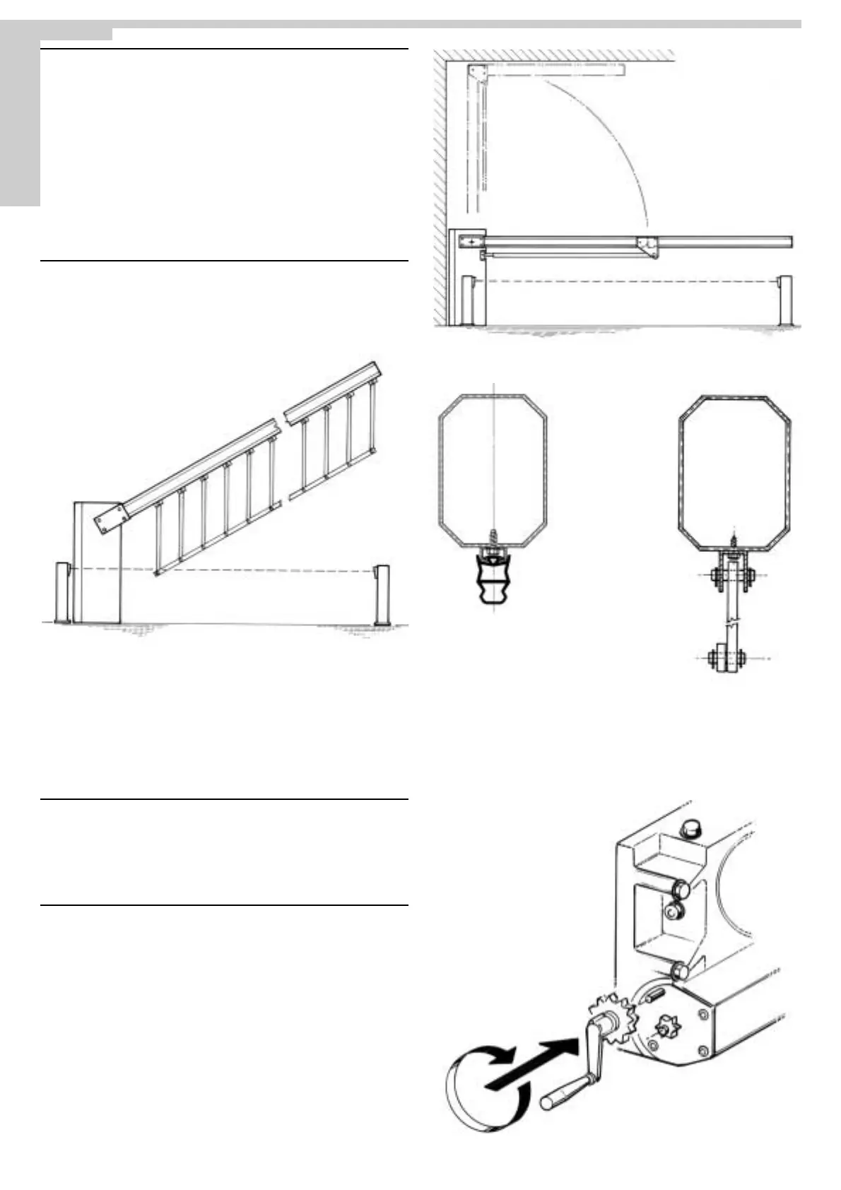
ASSEMBLING THE NORMAL BARRIER
After having cemented the fixing base in the position you prefer, fix the NORMAL unit,
using the nuts supplied and a setscrew wrench n.19.
Then fit the boom following the four steps below.
1 - Turn the release crank until you reach the stop in order to fit the boom in the
horizontal position (springs shall be under tension).
2°- Insert the boom hub in the bush you have fitted in one of the holes on both sides of
the column and then lock it to the reduction gear with the screw TSPEI 10x90.
3°- Working from the ground, insert the U-plate on the boom with the four screws
M8x110.
4°- Fix the boom by using a n. 13 wrench to tighten the four M8x110 bolts to the four nuts
and then apply the plugs to its ends.
Afterwards, substitute the hexagonal plug of the superior portion of the reduction gear
unit with the plug supplied to release the oil pressure, by using a setscrew wrench n. 24.
EMERGENCY RELEASE
Carry out only after having disconnected the power supply to the motor.
In the event of a power failure, you need to release the electric reduction gear In order to
operate the boom by hand.
1° - Open the front casing with your customized wrench.
2° - Insert the specific crank into the coupling of the reduction gear.
3° - Turn until you get the complete opening.
Fitting a hanging rack to an
aluminium boom (Picture.3-
5).
Fitting a photocell-type
safety strip to an aluminium
boom (Fig. 4).
Fig.2
Fig.3
Fig.4
Fig.5
Fig.6
 Loading...