EasyManua.ls Logo

RIB NORMAL User Manual

RIB NORMAL
72 pages
Go to English
To Next Page IconTo Next Page
Page #1 background imageLoading...
Page #1 background image
NORMAL
c P1-CRX
ITALIANO pag. 05 / FRANÇAIS pag. 18 / ENGLISH page 31 / DEUTSCH pag. 44 / ESPAÑOL pag. 57
Operatore
Operateur
Operator
Torantrieb
Operador
Alimentazione
Alimentation
Power Supply
Stromspannung
Alimentacion
Lunghezza max asta
Longueur maxi de la lisse
Max. boom lenght
Max. Baumlänge
Longitud máxima de la asta
Codice
Code
Code
Code
Codigo
NORMAL
230V 50Hz 6 / 7 m
AA50160
NORMAL ICE AA50162
Vedere pagina 15
Voir page 28
See page 41
Siehe Seite 54
Ver página 67
EL PRODUCTO SE ENTIENDE PARA EL CONTROL DE TRÀFICO VEHICULAR, Y NO PARA
TRÀFICO PEATONAL.
Aconsejamos, por lo tanto, aplicar las seguridades requeridas y carteles como
art. ACG9624, para que los peatones no choquen con el producto.
QUESTO PRODOTTO È DEDICATO AL CONTROLLO LED TRAFFICO VEICOLARE, NON A
QUELLO PEDONALE.
Si consiglia pertanto l’applicazione delle sicurezze richieste e di uno o più
cartelli di attenzione cod. ACG9624 per evitare il contatto dei pedoni con il
prodotto.
CE PRODUIT EST DÉDIÉ AU CONTRÔLE DU TRAFIC VÉHICULAIRE, ET NON À CELUI DES PIÉTONS.
Il est donc conseillé d’appliquer les règles de sécurité demandées et de signaler le danger
par un ou plusieurs panneaux ACG9624 afin d’éviter tout contact entre les piétons et le
produit.
THIS OPERATOR IS DESIGNED FOR THE VEHICLES ACCESS CONTROL AND NOT FOR
PEDESTRIANS.
Therefore, we higly recommend the use of safety devices and that of one or
more warning plates, art. ACG9642 to prevent the pedestrians interfering with
the operator.
DAS PRODUKT IST ZUR KONTROLLE VON WAGENVERKEHR, NICHT VON FUSSGÄNGER-
GEMEINT.
Wir weisen darauf hin, die geforderten Sicherheitszeichen, wie per Art.-Nr.
ACG9624 anzuhängen, um den Kontakt zwischen Fussgänger und Produkt zu
vermeiden.
Disegni tecnici per progetti
Dessins techniques pour les projets
Technical drawings for projects
Technische Zeichnungen für Projekte
Dibujos técnicos para proyectos.

Other manuals for RIB NORMAL

Question and Answer IconNeed help?

Do you have a question about the RIB NORMAL and is the answer not in the manual?

RIB NORMAL Specifications

General IconGeneral
Motor voltage24 Vdc
Operating temperature-20°C to +60°C
Protection levelIP54
Protection ClassIP54
Opening time6 seconds
Operation ModeAutomatic
Closing Time6 seconds
Power supply230V AC

Summary

Installation Safety Instructions

General Safety Precautions

Key safety warnings and instructions for personnel.

Installation Safety Guidelines

Essential steps and rules for correct product installation.

Environmental Compliance

WEEE Disposal Information

Information regarding the disposal of electrical and electronic equipment.

System Layout and Technical Data

Technical Characteristics

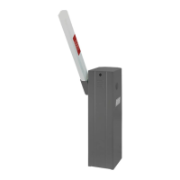
Description of the gearmotor, upright, and barrier boom.

Technical Specifications

Detailed technical specifications and parameters of the barrier.

Barrier Installation and Adjustment

Barrier Assembly Procedure

Step-by-step guide for assembling the barrier boom.

Limit Switch Adjustment

Instructions for setting the barrier's limit switches and stopper.

Balancing Spring Adjustment

Procedure for adjusting balancing springs based on boom configuration.

Emergency Release Operation

Steps for manually releasing the barrier in case of power failure.

Electric Connections and Control Panel

Control Panel Wiring Diagram

Schematic of the control panel connections and component layout.

Control Panel Features and Terminals

Detailed description of control panel inputs, outputs, and features.

Control Panel Settings and Programming

DIP Switch Settings

Configuration options using DIP switches for various functions.

Speed and Radio Programming

Adjusting slow speeds and programming radio transmitter codes.

Command Accessory Operations

How to use various command accessories and operating modes.

Safety Accessory Management

Configuration and operation of safety devices like photocells and edges.

Safety Device Functionality and Alarms

Safety Device Operation Details

In-depth details on safety device behavior and troubleshooting.

Visual and Sound Alarms

Explanation of alarm signals from blinkers, buzzers, and indicator lights.

Fault Diagnosis and Solutions

Troubleshooting common faults and their corresponding solutions.

Optional Accessories

Boom Arms and Racks

Details on different boom arm types and hanging racks.

Mounting Hardware

Components for mounting boom arms and base plates.

Support Structures

Various support columns and mounting hardware for the barrier.

Sensors and Communication Modules

Sensors, photocells, and loop detectors for vehicle detection.

Radio and Control Modules

Transmitters, radio modules, and control cards for extended functionality.

Photocell Connections and Autotest

Photocell Wiring Diagrams

Wiring diagrams for various photocell configurations and autotest.

Autotest Functionality Warning

Important warning regarding the AUTOTEST feature and jumper settings.

Related product manuals