LED
L1 (Yellow) indicates secondary power supply (12Vdc)
L2 (Red) indicates time settings
TIMER SETTINGS
To be performed with the barrier closed and the closing limit switch pressed.
NOTE: Safety devices are enabled during opening and therefore timer programming must
be performed without vehicle transit in the vicinity of the system.
Should transit occur, the barrier stops and must be closed again and the programming
procedure must be repeated.
If one of the safety device is engaged during closing, programming does not need to be
repeated as the times have already been memorised and the barrier will invert direction on
opening and close on the subsequent command.
The barrier is normally supplied with pre-set times. However, the standby time prior to
automatic closing is set at a few seconds only.
To modify this time setting as required, proceed as follows:
1) Use the manual release to close the barrier and ensure that the closing limit switch is
engaged by the cams; lock the barrier by tightening the release device.
2) Press S1 briefly; led L2 (red) illuminates.
3) Press S1 briefly; the barrier opens and stops when the opening limit switch is reached
(led 2 remains lit).
E
N
G
L
I
S
H
J1 TERMINAL BOARD
NL1 230V 50/60 Hz power supply
J2 CONNECTOR
Via an optional card (Relay card 1 code no. ACQ9075) this connector powers a garage
light with a time setting between 1 second and 3 minutes (max. 40 W).
Otherwise the connector can power an optional card to control an electromagnet
(supplied with column with magnet set code no. ACG8070).
For information regarding the auxiliary cards, request specific installation instructions.
J3 TERMINAL BOARD
L/L 230 V ac electronic flasher unit power supply
U Motor common
V/W Motor inverters
J4 TERMINAL BOARD
K-OUT N.O. contact; in normal operation mode (Fig. 8) operates as a sinusoidal
pulse (performs commands OPEN-STOP-CLOSE-STOP...); in park mode
(Fig.9) enables closing 1 second after vehicle transit.
IN-PARK N.O. contact; in park mode, if connected to a magnetic sensor or photocell, it
indicates the presence of a vehicle on approach to entry.
9 Open pushbutton (N.O.)
11 Close pushbutton (N.O.)
8 Contact common
J5 TERMINAL BOARD
Terminals for connection of antenna coax cable (type RG58-52)
N.B. Ensure that the earth does not touch the central wire on the cable as this will
restrict transmitters range.
J6 TERMINAL BOARD
10 Photocells and strips contact (N.C.)
LSS Contact for limit switch that enables motor deceleration on opening and
closing (N.O.)
2 Stop pushbutton (N.C.)
4 Limit switch contact to stop opening (N.C.)
7 Limit switch contact to stop closing (N.C.)
8 Contact common
D+/D- 12Vdc power supply for Photocells (ATTENTION to set them to this voltage!)
J7 CONNECTOR
Connector for radio receivers (12Vdc power supply).
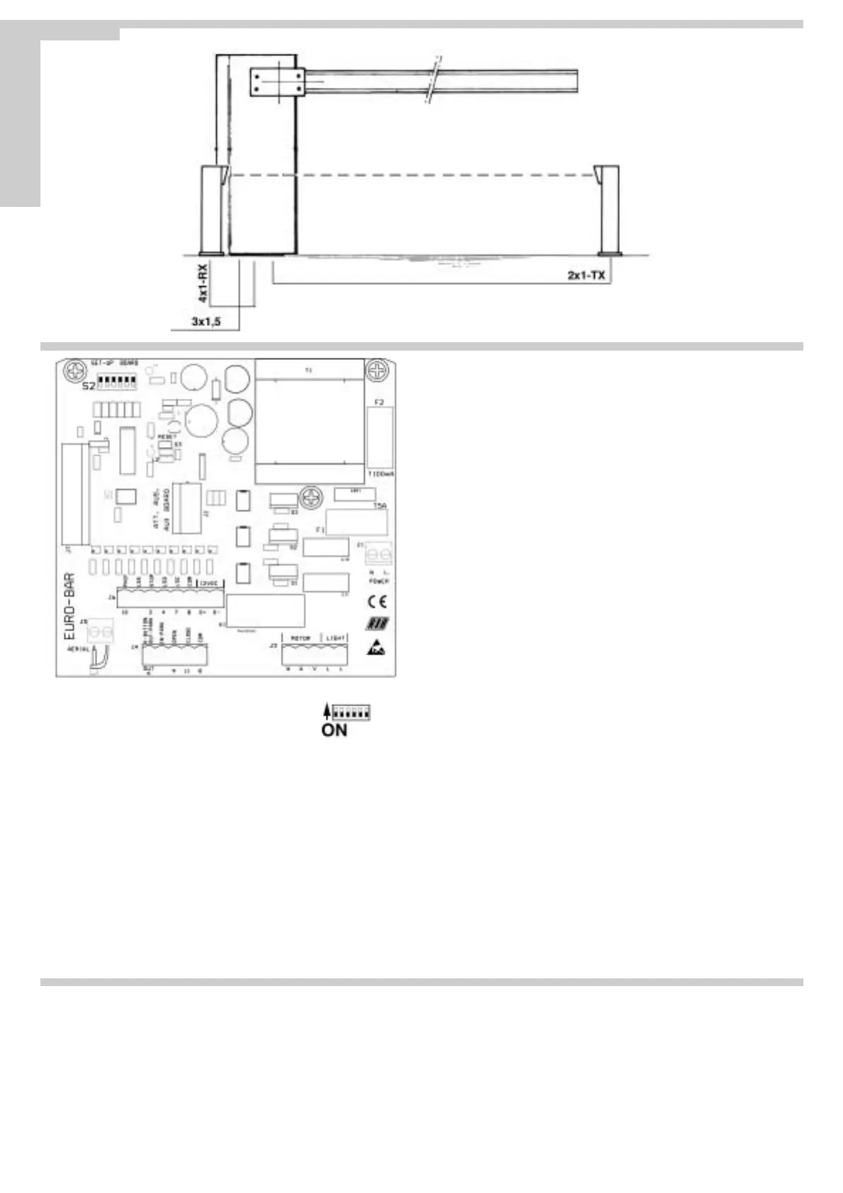
S2 - MICROSWITCHES FOR CONTROL UNIT SETTINGS
Dip1 For future use
Dip2 Flasher
ON fixed output, use flasher unit with card ACG7010.
OFF flasher output, use diamond line flasher unit ACG7050
Dip3 Photocell
ON stops movement during opening and closing
OFF stops movement during closing only
Dip4 Operation mode
ON park mode
OFF normal operation
Dip5 Standby time prior to automatic closing (max. 5 min.)
ON enabled
OFF disabled
Dip6 Pre-flasher
ON flasher will start 3 seconds before motor
OFF flasher will start at the same time as motor.
S3 - RESET
Each time the position of dipswitches is changed, loop S3 for at least one second
or the board will not accept the new settings (also possible using a screwdriver).
Pag. 20 di 36
Fig.10
 Loading...