Do you have a question about the Riello Burners PRESS 60 N/ECO 628 T and is the answer not in the manual?
| Brand | Riello Burners |
|---|---|
| Model | PRESS 60 N/ECO 628 T |
| Category | Burner |
| Language | English |
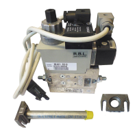
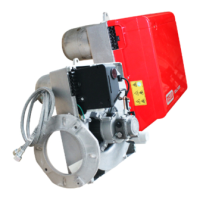
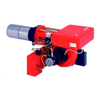
Lists components and accessories for the burner, including flexible tubes, seals, and fittings.
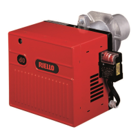
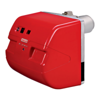
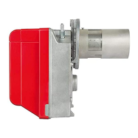
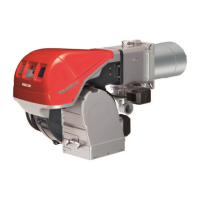
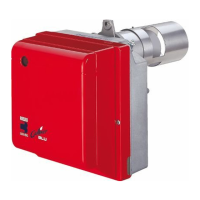
Provides detailed specifications like type, thermal power, fuel, electrical supply, motor, ignition transformer, and pump.
Includes diagrams and measurements for the burner and boiler plate dimensions.
Shows a graph illustrating the operating field based on combustion chamber pressure and thermal power.
Details different fuel oil supply systems like Gravity, Suction, and Loop systems with diagrams and specifications.
Explains the electrical system of the burner, including a diagram and component identification.
Details the electrical connections to the burner terminal strip, including wiring diagrams and cable entry information.
Provides a table of recommended nozzles and their flow rates at different pressures.
Specifies recommended pump pressures for light and heavy oil and explains flow rate variation.
Guides on adjusting the combustion head using a screw and shows a diagram for reference.
Explains the adjustment of the air damper motor using levers for different stages of operation.
Details the adjustment procedure for the air pressure switch and its function.
Explains how to adjust the atomisation temperature using a thermostat for optimal fuel atomisation.
Outlines the sequence of operations during burner start-up, including thermostat, motors, and valves.
Provides warnings and notes regarding the use of ecological fuels, including necessary precautions and burner differences.
Includes a warning about changing a fitting when operating with emulsified fuel oil.
Explains the colour code table for start-up sequence indications and their corresponding meanings.
Details the self-diagnostic system using the RED LED to identify operating faults and their probable causes.