Do you have a question about the Riello Burners MB 407/1 and is the answer not in the manual?
Details the instruction manual's role as an integral part of the product.
Outlines manufacturer's guarantee terms and conditions, and causes for invalidation.
Highlights risks associated with imprudent use of the gas train.
Defines user responsibilities for qualified personnel and adherence to safety instructions.
Explains the coding system for gas train models and their specifications.
Lists available gas train models with their corresponding codes.
Presents technical specifications and operating parameters for different models.
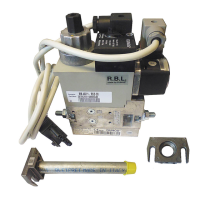
Lists and identifies the key components of the gas train assembly.
Provides a diagram and labels for the gas train components.
Details the physical dimensions and connection types of various gas train models.
Safety precautions for installation, including electrical disconnection and qualified personnel.
Guidelines for safe handling of the gas train to prevent injuries and damage.
Checks for consignment integrity and packaging disposal before installation.
Specifies the correct operational positions for the gas train to ensure proper function.
Procedure for installing the gas train, including leak checks, connections, and strain relief.
Wiring instructions for models using a 6-pin plug-socket connection to the burner.
Instructions for connecting gas trains to burners via a terminal board.
Electrical diagrams and connections for gas trains specified in Tab. G and Fig. 8.
Electrical diagrams and connections for gas trains specified in Tab. H and Fig. 9.
Safety guidelines for initial start-up, emphasizing qualified personnel and device checks.
Procedure for calibrating the pressure adjuster for optimal output pressure.
Details on pressure coupling requirements and potential need for stabiliser removal.
Instructions for adjusting the slow ignition delivery and steady state output of the valves.
Method for optimizing gas train delivery by adjusting valve and stabiliser settings.
Guidance to refer to the burner manual for low gas pressure switch adjustment.
Explanation of the valve leak detection device's operation, checks, and installation.
Safety precautions for maintenance, including electrical disconnection and fuel shut-off.
Recommends annual checks by manufacturer representatives or specialized technicians.
Operator requirements for performing checking and cleaning operations during maintenance.
Procedure for checking and replacing the gas train filter.
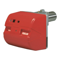
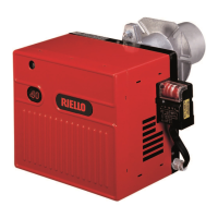
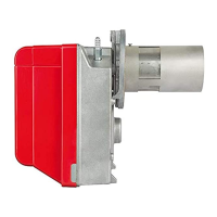
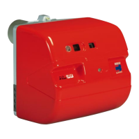
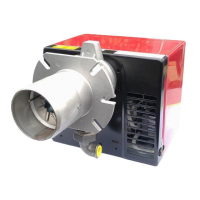
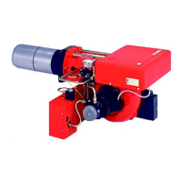
| Burner Type | Monoblock |
|---|---|
| Fuel Type | Light Oil |
| Air Regulation | Mechanical |
| Voltage | 230 V |
| Frequency | 50 Hz |
| Stages | Two stage progressive |