Technical description of the burner
7
20045701
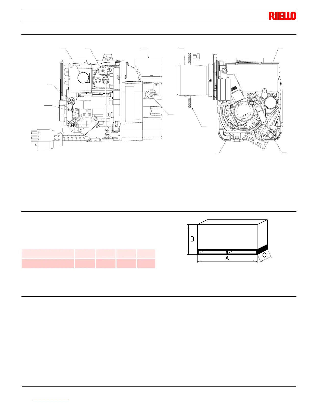
3.4 Burner description
1 Oil pump
2 Control box
3 Reset button with lock-out lamp
4 Flange with insulating gasket
5 Air damper adjustment screw
6 Pump pressure adjustment screw
7 Bleeder connection
8 Flame detector
9 Combustion head
10 Air intake (CF)
11 Motor
3.5 Packaging - weight - Approximate measurements
The burners are skid mounted. Outer dimensions of packaging are
indicated in Tab. B.
The weight of the burner complete with packaging is indicated in
Tab. B.
Tab. B
3.6 Standard equipment
1 - Burner head gasket
1 - Flange with insulating gasket
1 - Screw of by-pass pump
1 - Screw and nuts for flange
1 - 4 pin plug
1 - Hexagonal key
1 - Nipple 3/8 - 1/4
4 - Screws for flange to be fixed to boiler
1 - Nipple 3/8 - 3/8
2 - Pipe connectors
2 - Female adaptors 1/4 NPT
9
4
1
7
2
10
8
3
6
5
11
Fig. 1
D12187
inch A B C lbs
RDB 2.2R T1 BF FCX22
15
35
/
64“
11
39
/
64“
12
1
/
64“
24.3
RDB 2.2R T3 BF FCX30
15
35
/
64“
11
39
/
64“
12
1
/
64“
24.3
Fig. 2
D36