20045701
16
Installation
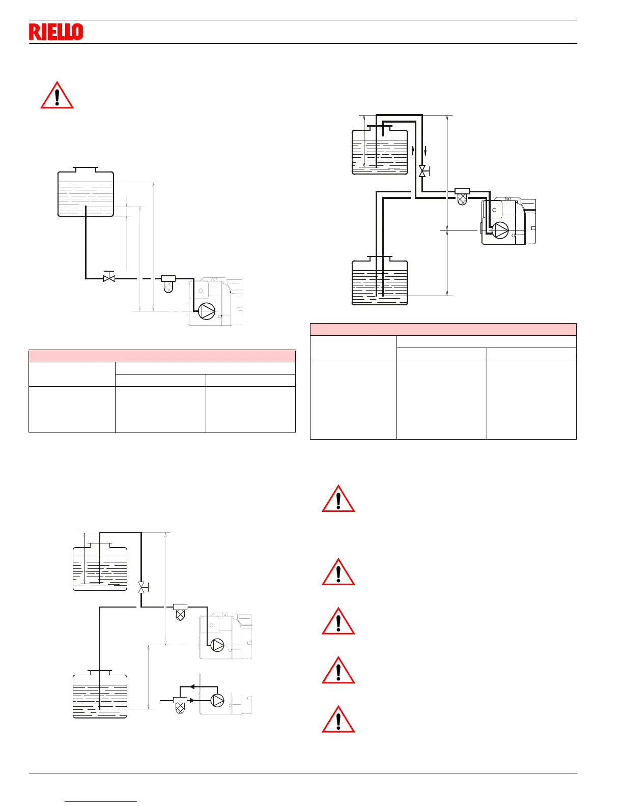
4.9.3 Priming pump
On the system in Fig. 11 it is sufficient to loosen the suction gauge
connection 6)(Fig. 10) and wait until oil flows out.
On the systems in Fig. 12 and Fig. 13 start the burner and wait for
the priming. Should lock-out occur prior to the arrival of the fuel,
await at least 20 seconds before repeating the operation.
The pump suction should not exceed a maximum of 0,4 bar (30 cm
Hg). Beyond this limit gas is released from the oil. Oil pipes must
be completely tight.
In the vacuum systems (Fig. 13) the return line should terminate
within the oil tank at the same level as the suction line.
In this case a non-return valve is not required. Should however the
return line arrive over the fuel level, a non-return valve is required.
This solution however is less safe than previous one, due to the
possibility of leakage of the valve.
H = difference of level
L = Max. lenght of the suction line
P = Max. lenght
WARNING
Before starting the burner, make sure that the tank
return line is not clogged.
Obstructions in the line could cause the sealing
organ located on the pump shaft to break.
SINGLE LINE SYSTEM-PIPE LENGHTS
H
ft
L ft
3/8” 12/”
1.5
3.0
5.0
6.5
33
65
130
195
65
130
260
325
H
P
min. 0.33 ft
D5741
Fig. 11
Fig. 12
H
D1842
P
H
TWO LINE SYSTEM-PIPE LENGHTS
H
ft
L ft
3/8” 12/”
0
1.64
3.29
4.93
6.58
9.87
11.5
115
100
80
65
50
25
20
330
330
330
295
230
100
65
WARNING
³ Pipe dope or Teflon tapes are NOT to be used
on any direct oil connection to the fuel pump.
³ The height ‘P’ in pipe length charts should not
exceed 13 feet (4 m).
³ The vacuum should not exceed 11.44 inches of
mercury.
WARNING
An external, appropriately listed and certified oil fil-
ter must be placed in the fuel line between the fuel
tank and the burner pump.
WARNING
ALWAYS KEEP THE VALVE FROM THE TANK
SHUT OFF IF THE BURNER IS SHUT DOWN FOR
AN EXTENDED PERIOD OF TIME.
WARNING
IT IS IMPORTANT THAT THE FUEL LINE BE
COMPLETELY SEALED AND FREE FROM AIR
LEAKS OR ANY INTERNAL BLOCKAGES.
WARNING
WHEN THE BYPASS PLUG IS INSTALLED, A
TWO-PIPE SYSTEM MUST BE USED OR FAIL-
URE OFTHE PUMP SHAFT WILL OCCUR.
D5740
Fig. 13
HP
H




 To Next Page