Do you have a question about the Riello RLS 1000/M C13 and is the answer not in the manual?
Statement of compliance with ISO/IEC 17050-1 and European Directives for the product.
Manufacturer's statement regarding NOx emission limits as per German standard.
Information on the proper use, interpretation, and importance of the instruction manual.
Explanation of danger classifications and warning symbols used throughout the manual.
Details on warranty conditions, exclusions, and manufacturer's liability limitations.
Importance of adhering to safety regulations and risks associated with improper equipment use.
Ensuring personnel are qualified and informed for safe operation and maintenance tasks.
Explanation of the coding system used to identify burner models and configurations.
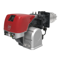
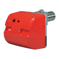
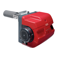
List of different burner models offered with their key specifications.
Categorization of burners based on country of destination and applicable gas types.
Comprehensive technical specifications including output, fuels, pressures, and environmental data.
Information on electrical requirements, motor types, and power consumption for the burner.
Weight details for different burner models, including packaging.
Detailed dimensions of the burner, with diagrams for installation reference.
Information on maximum and minimum output limits and relevant firing rate diagrams.
Details on test boiler dimensions and compatibility requirements for burner installation.
Detailed diagram and list of all components comprising the burner assembly.
Diagram and list of components found within the burner's electrical control panel.
List of standard equipment and spare parts included with the burner for installation.
Essential safety warnings for handling and operating the LFL1.333.. control box.
Specifications for the control box, including voltage, power, and environmental conditions.
Safety warnings and precautions for the SQM10.1 servomotor installation and use.
Technical specifications for the servomotor, including operating voltage and environmental conditions.
Critical safety instructions to follow during the burner installation process.
Guidelines for safely handling and moving the burner during the installation phase.
Essential checks before installation, including consignment and burner identification.
Specifies the allowed operating positions for the burner and prohibited configurations.
Steps for preparing the boiler, including drilling the plate and setting blast tube length.
Instructions for physically mounting the burner onto the boiler, ensuring an airtight seal.
Procedure for safely opening the burner to access internal parts for maintenance or adjustment.
Correct placement of the ignition electrode relative to the ignition pilot for optimal function.
Steps for installing the nozzle, including tool usage and torque recommendations.
List of recommended nozzles, their specifications, and complete nozzle ranges available.
Procedure for adjusting the combustion head using levers and selecting holes based on output.
Description of the double-pipe system for oil supply, including tank height considerations.
Explanation of the loop circuit for oil supply, useful when self-priming is difficult.
Instructions for correctly connecting flexible hoses to the pump supply and return lines.
Schematic diagram illustrating the hydraulic circuit of the burner for reference.
Procedures for calibrating the pressure variator on both return and delivery lines.
Key technical specifications for the burner pump, including delivery rates and pressures.
Detailed steps for priming the pump, including safety precautions and troubleshooting.
Diagrams and descriptions of various gas feeding line configurations (MBC, DMV, CB).
Information on gas trains approved per EN 676 and their selection criteria.
Safety procedures for gas train installation, including leak checks and electrical disconnection.
How to calculate gas pressure drop across the combustion head and butterfly valve.
Connecting the pilot gas train to the main gas supply or LPG cylinder.
Procedure for adjusting ignition pilot burner gas pressure and checking flame stability.
Information on the spray lance for light oil and the 3-way valve for activation.
Critical safety guidelines for electrical wiring installation, including disconnections and earthing.
How to route supply cables and external connections through cable grommets.
Explanation of the thermal relay's role in motor protection and its calibration procedure.
Essential safety measures and checks before the initial burner start-up.
Key adjustments required before igniting the burner on light oil operation.
Procedure for igniting the burner when using light oil as fuel.
Necessary adjustments before igniting the burner on gas, including pressure checks.
Steps for starting the burner when using gas as fuel, including selector settings.
Procedure and troubleshooting for igniting the burner on gas fuel.
Methods for selecting and changing between different fuel types (oil/gas).
Detailed guide on adjusting the servomotor cams for output and air control.
Methods for adjusting combustion air to achieve optimal fuel/air synchronization.
Steps for setting maximum, minimum, and intermediate burner outputs.
Procedures for calibrating the air/fuel ratio for optimal combustion.
Detailed procedure for calibrating the burner for both oil and gas operation.
Adjusting the air pressure switch and checking CO levels for safe operation.
Procedure for setting the maximum gas pressure switch.
Procedure for setting the minimum gas pressure switch.
Detailed sequence of operations during burner start-up.
Description of how the burner operates in response to heat requests.
Handling of flame loss during operation and ignition failure scenarios.
Final checks to be performed with the burner operating and after shutdown.
Essential safety rules to follow before and during maintenance operations.
Guidelines on maintenance frequency and specific checks/cleaning procedures.
Step-by-step guide to safely open the burner for internal access.
Instructions for reassembling the burner after maintenance.
List of common faults, their causes, and recommended solutions for light oil operation.
Diagnosing and resolving issues related to flame appearance, smoke, and ignition.
Addressing faults like failure to reach second stage, lockout, or uneven fuel supply.
Diagnosing and resolving issues with noisy pumps, unstable pressure, and priming.
Troubleshooting combustion faults, dirty heads, and burner lockout during operation.
List of faults, causes, and solutions for gas operation, including start-up and lockout issues.
Troubleshooting scenarios involving gas lockout, flame simulation, and ignition pulsations.
Kits for output power regulation, including probes and regulators.
Kits for analogue signal conversion with potentiometers and converters.
Kit designed to reduce burner noise levels.
Kit for remotely selecting the fuel type for the burner.
An index listing all electrical diagrams and layout sheets within the appendix.
Explanation of how references (sheet number, coordinates) are used in electrical diagrams.
Various functional layouts, diagrams, and wiring kits for the electrical panel.
A comprehensive key explaining all abbreviations and symbols used in the wiring diagrams.
| Category | Indoor Fireplace |
|---|---|
| Model | RLS 1000/M C13 |
| Manufacturer | Riello |
| Fuel Type | Natural Gas / LPG |
| Electrical Supply | 230 V ± 10% 50 Hz |