Do you have a question about the Riello RS/M Series and is the answer not in the manual?
Manual's purpose, content, and handling.
Manufacturer's guarantee, responsibilities, and voiding conditions.
General safety principles and potential dangers.
Requirements for qualified personnel and user responsibilities.
Table of burner models, codes, voltage, and flame safeguard.
Specifications for output, fuel, pressure, temperature, and noise.
Detailed electrical specs for different models and voltages.
Diagrams and table of physical burner dimensions.
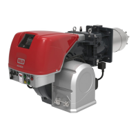
List of standard components included with the burner.
Graphs and tables showing burner output ranges and conditions.
Adjusting burner performance for altitude and air temperature.
Guidance on required furnace dimensions for optimal performance.
Detailed breakdown and illustration of burner components.
Info, data, and safety warnings for the RFGO-A13 control box.
Specs, warnings, and environmental conditions for the SQM41 servomotor.
Essential safety precautions during burner installation.
Guidelines for safely handling and moving the burner.
Steps to verify burner condition and packaging upon receipt.
Steps for boiler preparation, including drilling mounting plates.
Guidance on selecting the correct blast tube length based on boiler requirements.
Procedure for calibrating the combustion head for optimal performance.
Steps for securely mounting the burner onto the boiler.
Adjusting the combustion head for air and gas delivery based on maximum output.
Specific steps for adjusting the air damper.
Specific steps for adjusting the gas butterfly valve.
Procedure for adjusting the pilot flame for correct ignition.
Diagrams and instructions for making electrical connections.
Safety precautions and procedures for connecting the gas supply.
Steps for connecting the main gas train and pilot gas train.
Requirements for the gas train components and safety checks.
Calculating manifold pressure based on combustion chamber pressure.
Safety notes and procedures for electrical wiring.
Details on using the spring-loaded terminal system.
Guidelines for feeding cables through grommets.
Procedures for calibrating electro-mechanical and electronic thermal relays.
Wiring diagrams for connecting motors at different voltages.
Wiring diagrams for connecting motors at 575V.
How to reverse motor rotation by swapping phases.
Description of burner starting, steady state, and failure modes.
Sequence of operations during burner startup.
How the burner operates with external control signals.
What happens when the burner fails to ignite.
Response when the flame extinguishes during operation.
Crucial safety measures for the initial burner startup.
Steps for adjusting gas pressure switches and purging gas line.
Overview of the servomotor's function and components.
Procedures for disengaging gears, adjusting cams, and positioning the servomotor.
How to initiate burner startup and check fan blade rotation.
Calibrating air, maximum gas, and minimum gas pressure switches.
Steps to adjust the air pressure switch.
Steps to adjust the maximum gas pressure switch.
Steps to adjust the minimum gas pressure switch.
What to expect during the initial burner firing sequence.
Steps for calibrating the burner's output and deliveries.
Adjusting the pilot flame.
Setting the maximum burner output.
Setting the minimum burner output.
Adjusting gas and air delivery for intermediate outputs.
Calibrating range adjustment potentiometers for modulation.
Setting the analog signal range for high and low fire positions.
Final operational checks after calibration and adjustment.
Safety precautions before performing maintenance tasks.
Recommended schedule and procedures for burner maintenance.
Recommended frequency for gas combustion system checks.
Procedure for a safety test with the gas valve closed.
Procedures for checking and cleaning components like combustion head and servomotor.
Explains the meaning of different LED indicators on the control device.
How to enable and use the check mode for diagnostics.
How the control device indicates lock-out or emergency stop conditions.
Table showing LED status during normal operation and check mode.
Methods for resetting the control device after a lock-out.
Table showing LED lock-out codes and their meanings.
List and diagrams of available spare parts for the burner.
Details on optional kits for combustion head lengthening and LPG operation.
A template for recording burner startup parameters and test results.
| Model Series | RS/M Series |
|---|---|
| Ignition Type | Electronic |
| Fuel Type | Gas |
| Heat Output | Varies by model |
| Dimensions | Varies by model |
| Weight | Varies by model |
| Efficiency | Varies by model (typically >90% gross efficiency) |
| Remote Control | Optional |