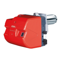
Do you have a question about the Riello RS 68/M BLU and is the answer not in the manual?
Guidance on manual usage, symbols, and delivery of instructions.
Details on manufacturer's guarantee and limitations of liability.
Overview of safety principles and potential hazards.
Requirements for qualified personnel and user responsibilities.
Explanation of the alphanumeric code used for burner identification.
Classification of burners based on country of destination and gas category.
List of available burner models, power supply, and codes.
Specifications including output, fuel, pressure, and noise levels.
Details on electrical supply, fan motor, and ignition transformer.
Physical dimensions of the burner, with diagrams and measurements.
Charts showing burner output versus combustion chamber pressure.
Information on test boilers and combustion chamber requirements.
List of components included with the burner.
Detailed breakdown of burner components with numbered diagram.
Identification and function of components in the electrical panel.
Important notes, technical data, and wiring for the RFGO-A22 control box.
Details on the servomotor, its function, technical data, and environmental conditions.
Essential safety precautions to be followed during installation.
Instructions for safe handling and transport of the burner.
Checks to perform upon receiving the burner, including consignment and label.
Recommended and prohibited installation orientations for the burner.
Steps for preparing the boiler, including door thickness and plate boring.
Procedure for drilling the boiler plate for burner installation.
Guidance on selecting the appropriate blast tube length.
Instructions for correct positioning of the flame probe and ignition electrode.
Steps for physically mounting the burner onto the boiler structure.
Procedure for pre-calibrating the combustion head for optimal performance.
Detailed instructions for adjusting the combustion head for optimal output.
Safety precautions and procedures for connecting the gas supply line.
Key components and diagrams for gas feeding lines.
Information on selecting and installing the gas train.
Step-by-step guide for installing the gas train.
Table and explanation of gas pressure drops for different outputs.
Safety notes and procedures for electrical wiring connections.
Guidelines for routing supply cables and external connections.
Procedure for calibrating the thermal relay for motor protection.
How to check and correct the fan motor rotation direction.
Critical safety measures for the initial burner start-up.
Essential adjustments to be made before the first ignition attempt.
Procedure for adjusting the servomotor for air damper and gas butterfly valve.
Steps for powering up the burner and initial checks.
Troubleshooting and adjustments for burner ignition.
Steps for optimizing burner performance through adjustments.
Guidelines for setting the ignition output based on safety standards.
Procedure for setting the burner to its maximum output level.
Procedure for setting the burner to its minimum output level.
Adjusting the burner for intermediate output levels.
Final calibration of air and gas pressure switches.
Procedure for adjusting the air pressure switch for safety.
Adjusting the maximum gas pressure switch.
Adjusting the minimum gas pressure switch.
Verifying the flame detection system's functionality.
Overview of the burner's operational phases and states.
Essential safety precautions for performing maintenance tasks.
Recommended maintenance schedule and procedures.
Procedures for checking and cleaning burner components.
Information on the lifespan and replacement of safety components.
Steps for safely opening the burner for inspection or maintenance.
Procedure for reassembling the burner after maintenance.
Explanation of LED indicators and their meaning during operation.
How to use the check mode for diagnostics and commissioning.
Understanding and handling lock-out and emergency stop conditions.
Table of LED codes indicating specific faults and troubleshooting steps.
Detailed explanation of fault codes, their causes, and solutions.
Kits for output control (temp, pressure, remote setpoint) and signal conversion.
Kits for burner components (head, soundproofing, spacer) and gas train connections.
Kits for flame detection (UV sensor), safety (circuit breaker), and gas type (LPG).
Tubes kit, gas flange kit, and potentiometer kit for installation and adjustment.
List of available electrical panel layout diagrams and their references.
Explanation of how sheet numbers and coordinates are used for reference.
Functional wiring diagram for the RFGO-A22 control box.
Operational wiring diagram for the RFGO-A22 control box.
Wiring diagrams for electrical power supply and safety devices.
Wiring diagrams for gas valves, leak detection, and lockout/reset.
Wiring diagrams for modulation inputs and probe connections.
Glossary of symbols and terms used in the wiring diagrams.
