Do you have a question about the Riello RS 810/M BLU and is the answer not in the manual?
Details about the manual, hazards, and warning symbols.
General safety principles, hazard overview, and requirements for trained personnel.
Details naming conventions, models, categories, and technical specifications of the burner.
Specifies electrical requirements, dimensions, and burner output capabilities.
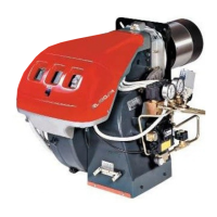
Illustrates and lists the various parts and components of the burner assembly.
Technical specifications and warnings for the RFGO-A22 control box and SQM41 servomotor.
Critical safety precautions and guidelines for safely handling the burner during installation.
Initial checks, boiler preparation steps, including mounting and internal access procedures.
Steps for boiler preparation, blast tube selection, and gas feeding procedures.
Guidelines for safe and correct electrical wiring, including cable routing and grommets.
Essential safety measures and pre-ignition adjustments required before the initial burner start-up.
Step-by-step guide for burner start-up, ignition, and servomotor adjustments.
Synchronizing air/fuel, and setting burner outputs (max, min, intermediate).
Calibration of pressure switches and descriptions of burner operation sequences and failure modes.
Critical safety warnings, maintenance frequency, and procedures for checking/cleaning components.
Procedures for burner access, reassembly, and performing safety tests with gas feed closed.
Explanation of LED indicators, their meanings in different states, and the check mode function.
Managing lock-out conditions, emergency stop, and understanding LED indications for operating status.
Methods for resetting the control device and understanding LED fault codes for diagnosis.
Detailed tables listing faults, their causes, and corresponding remedies identified by LED indicators.
Further fault code details, covering remaining issues and necessary corrective actions for system errors.
Lists available accessory kits, probes, potentiometers, and soundproofing/spacer kits.
Provides an index of electrical panel layouts and explains reference notations used in the diagrams.
Schematic diagram illustrating the main power connections for the burner and its components.
Functional schematics showing the operational logic and interconnections of burner systems.
Functional diagrams specific to the RFGO-A22 control unit and its operational layout.
Wiring diagrams for the servomotor control, setpoint inputs, and climatic compensation.
Wiring for safety devices, ancillary indicators, and gas valve leak detection systems.
A comprehensive key defining the symbols and terms used in the wiring diagrams.