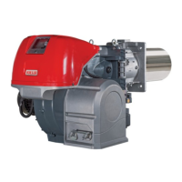
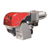
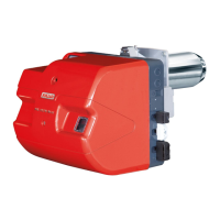
Do you have a question about the Riello RS 120/M BLU and is the answer not in the manual?
Details product compliance with standards and directives.
Guidance on manual usage, symbols, delivery, and manufacturer responsibility.
Identifies hazard levels, danger symbols, and protective equipment requirements.
Outlines manufacturer's guarantee terms and responsibility limitations.
Emphasizes safe operation, adherence to regulations, and potential risks.
Defines user responsibilities for training personnel on safe operation and procedures.
Explains the coding system for burner series, fuel, size, and emission.
Details burner classifications based on country and gas category.
Lists burner models, power supply, start-up type, and codes.
Provides key technical specifications like output, fuel, pressure, and noise levels.
Details electrical supply, fan motor, ignition transformer, and power absorption.
Illustrates burner dimensions and provides measurement details for different models.
Shows output curves based on combustion chamber pressure and thermal power.
Details test boiler requirements and combustion chamber dimensions for performance.
Lists standard components supplied with the burner for installation.
Diagram and list of main burner parts, including combustion head, electrodes, and controls.
Diagram and list of components within the burner's electrical panel.
Details the function, technical data, and safety notes for the RFGO-A22 control box.
Describes the servomotor's role, technical data, and installation notes.
Highlights essential safety steps and warnings during the burner installation process.
Provides guidelines for safely handling, moving, and storing the burner unit.
Outlines checks for consignment integrity, burner labels, and model characteristics.
Specifies acceptable and prohibited installation positions for safe and correct operation.
Covers boiler suitability, front door thickness, and blast tube length considerations.
Details the correct placement and dimensions for the probe and ignition electrode.
Step-by-step instructions for physically mounting the burner to the boiler assembly.
Instructions for pre-calibrating the combustion head, especially for area B settings.
Provides methods for adjusting air and gas for optimal combustion based on output.
Details gas supply safety, components, and connection methods for different gas trains.
Covers gas train selection, installation, and pressure drop considerations.
Provides data on gas pressure drops and requirements for burner operation.
Guidelines for safe and correct electrical wiring, including safety notes and cable passage.
Explains how to calibrate and test the thermal relay to protect the motor.
Procedure for verifying and correcting the fan motor's rotation direction.
Critical safety guidelines to follow before and during the initial burner start-up.
Steps for adjusting gas supply, pressure switches, and air settings before ignition.
Details how to adjust the servomotor cams for damper and valve control.
Describes the burner start-up process, fan rotation, and electrical checks.
Covers ignition attempts, lockout conditions, and ignition output requirements.
Guides on adjusting the burner's maximum and minimum output levels.
Adjusting burner output for intermediate positions and gas delivery fine-tuning.
Procedure for final calibration of air and gas pressure switches.
Describes steady-state operation, output modulation, and lockout conditions.
Essential safety procedures and precautions to follow during maintenance tasks.
Outlines the recommended maintenance schedule and safety tests, including dry tests.
Details checks for combustion head, fan, burner, gas leaks, and filter cleaning.
Lists safety components and their specified replacement lifecycles or operation cycles.
Step-by-step instructions for safely opening and reassembling the burner unit.
Explains the meaning and status indicated by each LED on the burner's control panel.
Guide to using the check mode for diagnostics during start-up or maintenance.
Details how the flame control handles lock-out conditions and emergency stops.
Table showing LED states for various operating statuses and check modes.
Procedures for resetting the control device after lock-out conditions or emergency stops.
Identifies error codes indicated by LEDs and general troubleshooting advice.
Detailed table mapping LED patterns to specific faults, causes, and remedies.
Provides detailed explanations and solutions for identified fault codes and their causes.
Continues the detailed mapping of faults, causes, and recommended solutions.
Provides further fault explanations and troubleshooting steps for various error conditions.
Details kits for controlling temperature and pressure in modulating burner operation.
Information on the extended head kit for specific burner models.
Details for the soundproofing box kit to reduce burner noise.
Information on the spacer kit for burner installation.
Details for the continuous purging kit used with gas flange kits.
Information on the relay interface kit for burner control.
Details for the UV sensor kit used for flame detection.
Information on the differential circuit breaker kit for electrical protection.
Details for the LPG kit used for specific fuel types.
Information on the tubes kit for gas train connections.
Reference to manuals for gas trains compliant with EN 676 standards.
Explains how to navigate and interpret the electrical panel layout diagrams.
Illustrates the functional wiring and component layout for the RFGO-A22 control box.
Highlights the installer's role and responsibility for electrical wiring connections.
Depicts the functional wiring and component layout for the RWF50 regulator.
| Fuel Type | Light Oil |
|---|---|
| Voltage | 230 V |
| Frequency | 50 Hz |
| Burner Technology | Low NOx |
| Air Pressure Switch | Yes |
| Control Box | Integrated |
| Stages | Two stage |
| Burner Output | 300 - 1200 kW |
| Type | Monoblock |

