Do you have a question about the Riello RS 190/M and is the answer not in the manual?
Crucial safety instructions to follow if you smell gas, emphasizing no electrical contact and ventilation.
Warning against storing flammable or hazardous materials near fuel burning appliances.
Highlights risks of improper installation, adjustment, alteration, service, or maintenance, advising professional consultation.
Details technical specifications for the RS 190/M model, including output, fuel, and operational parameters.
Lists different codes and voltages associated with the RS 190/M burner models.
Information on optional kits, such as the LPG operation kit, and gas train requirements.
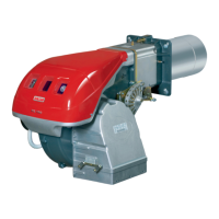
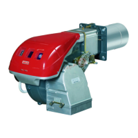
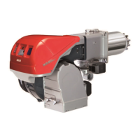
Detailed list and description of all numbered components of the burner assembly (1-27).
Provides packaging details, weight, and maximum physical dimensions of the burner.
Lists the essential components and parts that come standard with the burner unit.
Illustrates the burner's output variation (firing rate) based on combustion chamber pressure.
Specifies the minimum diameter and length required for the combustion chamber based on firing rates.
Table detailing pressure losses along the gas supply line at different burner outputs.
Guides on calculating maximum burner output and required gas pressure at test points.
Instructions for preparing the boiler mounting plate according to provided dimensions.
Guidance on selecting the appropriate blast tube length and insulation requirements.
Step-by-step process for physically mounting the burner onto the boiler securely.
Details on setting up and adjusting the pilot for correct ignition, including jumper settings.
Explains adjustments for air and gas flow to achieve optimal combustion based on burner output.
Procedures for refitting the burner after combustion head adjustments, including cable connections.
Instructions for connecting the main gas train to the burner, including safety valves placement.
Guidelines for connecting the pilot gas line to the designated burner attachment.
Procedures for adjusting low gas, high gas, and air pressure switches before initial operation.
Instructions for purging air from the gas line and using a manometer for pressure checks.
Describes the servomotor's role in regulating air damper and gas butterfly valve.
Explains the functions of cams and trim potentiometers for modulating output and limits.
Details the step-by-step process for starting the burner, including mode selection.
Guides on setting the burner's maximum and minimum output levels using trim potentiometers.
Instructions for setting intermediate output levels and optimizing combustion.
Detailed procedure for adjusting the air pressure switch for safety and optimal operation.
Instructions for adjusting high and low gas pressure switches to prevent lock-out.
Explains the ionisation system for flame detection and how to measure the ionisation current.
Covers maintenance of combustion head, servomotor, and general burner components for optimal performance.
Step-by-step guide on safely opening and closing the burner for inspection and maintenance.
Illustrates the factory wiring layout for the Siemens LFL control with burner-mounted components.
Details specific wire changes required for continuous fan operation mode.
Provides field wiring diagrams and tables for electrical connections, including voltage considerations.
Important notes regarding thermal overload settings, power supply, and intermittent operation requirements.
Shows the factory wiring diagram for systems using a remote control panel for the flame safeguard.
Table of correction factors F for adjusting burner firing rates based on air temperature and altitude.
Step-by-step guide to calculate equivalent delivery and check if the output point is within the firing rate range.
Describes the detailed sequence of operations during burner startup for full modulation and low-high control.
Explains how the servomotor controls output based on boiler pressure or temperature during steady state.
Details the lock-out conditions for firing failures and accidental flame loss during operation.
Explains the meaning of symbols indicating specific fault conditions like no start, startup interruption, or lockout.
Lists common causes for burner lock-out, such as flame supervision faults or pressure issues.
Template fields for recording gas and oil operation data, including CO2, O2, and firing rates.
Sections for documenting control settings like setpoints, pressures, and additional notes during startup.
| Model | RS 190/M |
|---|---|
| Fuel Type | Natural Gas |
| Voltage | 230 V |
| Frequency | 50 Hz |
| Electrical Supply | Single phase |
| Type | Burner |