Do you have a question about the Riello RS 100 and is the answer not in the manual?
Details the progressive two-stage operational capability of the gas burners.
Statement of compliance with ISO/IEC 17050-1, listing technical standards and directives met.
Information on the importance, content, and proper use of the instruction manual.
Explanation of hazard levels, specific dangers, and warning symbols used throughout the manual.
Procedures for receiving the burner system and handling the instruction manual.
Outlines the manufacturer's warranty conditions and limitations of responsibility.
Overview of safety principles in burner design and operation, highlighting potential risks.
Requirements for qualified personnel and user's responsibility for safe operation.
Details the coding system used to identify burner models, fuel types, and settings.
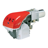
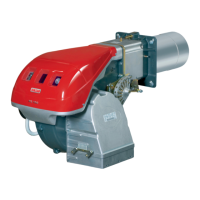
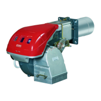
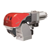
Lists the different burner models, including their type and voltage specifications.
Specifies burner categories based on country of destination and gas type compatibility.
Presents essential technical data including power, fuel consumption, and noise levels.
Details electrical supply requirements, fan motor, and ignition transformer specifications.
Provides dimensional drawings and measurements for the burner components.
Lists the standard equipment and spare parts included with the burner.
Explains one-stage and two-stage operation, with charts showing firing rates.
Information regarding compatibility with test boilers and combustion chamber dimensions.
Illustrated breakdown and description of individual burner components.
Explanation of control box and motor lockout states and reset procedures.
Specifications, environmental conditions, and components of the RMG88 control box.
Technical data, assembly notes, and important safety information for the servomotor.
Essential safety measures to be followed before and during the burner installation process.
Guidance on safely handling the burner and verifying the contents of the consignment.
Specifies the acceptable and prohibited operating positions for burner installation.
Instructions for preparing the boiler plate and selecting the correct blast tube length.
Procedures for accessing internal combustion head parts and performing pre-calibration.
Correct placement of the flame probe and ignition electrode to ensure proper function.
Step-by-step guide for adjusting the combustion head for optimal air and gas flow.
Description and diagrams of the components that make up the gas feeding line.
Instructions for installing the gas train and maintaining correct gas pressure.
Methods for calculating burner output based on gas pressure measurements and tables.
Crucial safety notes for electrical wiring, including earthing and cable routing.
Guidelines for routing supply cables and external connections through cable grommets.
Steps for calibrating the thermal relay to protect the motor from excessive absorption.
Essential safety checks and personnel requirements for the initial burner start-up.
Necessary adjustments and checks performed on the burner before ignition.
Detailed description of the sequence of operations during the burner start-up process.
Procedure for burner ignition and steps to take if ignition fails.
Guidance on adjusting burner output and ignition levels according to standards.
Setting the first stage output and adjusting air and gas delivery via servomotor.
Adjusting intermediate outputs and air delivery by modifying cam profiles.
Procedure for adjusting the air pressure switch for correct operation and safety.
Steps to adjust the minimum gas pressure switch for uniform burner operation.
Verification of the ionisation system's functionality for flame detection.
Details on adjusting the servomotor levers to control the air damper positions.
Describes burner start-up, steady-state operation with remote controls, and shutdown.
Actions to take in case of ignition failure or flame loss during operation.
Explanation of diagnostic codes indicated by control box LEDs during start-up.
Procedures for resetting the control box and interpreting visual fault indicators.
Critical safety measures to follow before performing any maintenance tasks.
Guidelines for periodic maintenance frequency and performing safety tests.
Procedures for inspecting and cleaning combustion head, filter, burner, and fan.
Instructions for maintaining the boiler, checking for gas leaks, and cleaning the flame window.
Guidance on combustion analysis and safety component replacement intervals.
Step-by-step guide for safely opening the burner for internal access.
Instructions for correctly reassembling and closing the burner after maintenance.
Identifies causes and remedies for lockouts and lack of flame based on signal blinks.
Solutions for burner issues like no start, continuous cycling, or ignition problems.
Accessory for protecting the burner against radio frequency interference.
Kit to extend the burner head for specific installation requirements.
Kit that enables the burner to operate using LPG as fuel.
Accessory designed to reduce vibration during burner operation.
Kit used for spacing components during the installation process.
Kits for managing the burner's pre-purging and post-purging cycles.
Accessory designed to reduce noise emissions from the burner.
Provides an index for electrical diagrams and explains the system of reference indicators.
Presents detailed functional and operational schematics of the burner's electrical panel.
Specific electrical panel layout diagram for the RS 70 burner model.
Specific electrical panel layout diagrams for RS 100 and RS 130 burner models.
Details electrical power supply configurations and safety devices for the RS 70 model.
Details electrical power supply configurations and safety devices for RS 100/130 models.
Explains the wiring symbols used and describes the burner terminal strip.
| Model | RS 100 |
|---|---|
| Fuel Type | Light Oil |
| Voltage | 230V |
| Frequency | 50Hz |
| Air Pressure Switch | Yes |
| Stages | Two Stage |
| Control Box | Riello |
| Type | Monoblock gas burner |
| Nozzle Size | According to the boiler's requirements |
| Nozzle Pressure | According to the boiler's requirements |