Do you have a question about the Riello RS 150/M and is the answer not in the manual?
Guidance on the proper use, importance, and content of the instruction manual.
Details on how the manual should be delivered and its contents.
Manufacturer's guarantee terms and conditions, and responsibility clauses.
Overview of safety principles and the importance of prevention measures for burner operation.
Requirements for qualified personnel and user responsibilities for safe operation and maintenance.
Explanation of the coding system used to identify burner models and their specifications.
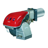
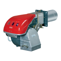
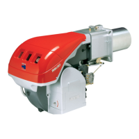
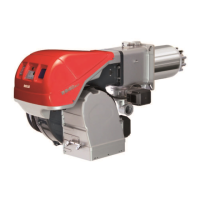
List of available burner models with their corresponding voltage, start-up, and code numbers.
Detailed technical specifications, including power, fuels, pressures, and electrical data.
Diagram and table showing the maximum physical dimensions of the burner.
Guidance on selecting the burner's maximum and minimum output based on performance diagrams.
Critical safety instructions and precautions to be followed during the burner installation process.
Steps to verify consignment integrity and burner characteristics before installation.
Specifies the acceptable operating positions for the burner and prohibits certain positions for safety.
Guidance on adjusting the combustion head, air, and gas for optimal burner calibration.
Essential safety precautions and procedures for connecting the gas supply line to the burner.
Essential safety precautions and requirements for performing the initial start-up of the burner.
Pre-ignition checks and adjustments for gas train, pressure switches, and air pressure.
Procedure for initiating burner start-up, including checks on fan rotation and solenoid status.
Detailed steps for adjusting ignition, maximum, minimum, and intermediate burner outputs.
Detailed sequence diagrams for normal ignition and burner operation without modulating kit.
Crucial safety instructions and precautions to be followed before and during maintenance.
Overview of essential maintenance tasks, frequency, and safety requirements.
Step-by-step instructions for safely opening the burner for inspection and maintenance.
Functionality for checking flame detection time using LED signals and related corrective actions.
Details and code for the long head kit accessory for the RS 150/M burner.
Information on the kit for modulating operation, including required components and codes.
Details and code for the PC interface kit accessory.
Details and codes for kits enabling LPG operation of the burner.
Information on the radio disturbance protection kit and when it is recommended.
Index listing the different electrical panel layout diagrams available in the appendix.
Explanation of how references (sheet number, coordinates) are indicated in the wiring diagrams.
Functional layout diagram for the RMG/M control box operating at 230V.
Overall functional diagram illustrating the burner's electrical system.
Wiring diagram detailing the installer's responsibilities for 230V electrical connections.
Functional layout diagram for the RWF40 output power regulator.
| Fuel Type | Light Oil |
|---|---|
| Burner Technology | Monoblock |
| Air Pressure Switch | Yes |
| Voltage | 230V / 50Hz |
| Operation | Two-stage |
| Control Box | Riello RMG |