Do you have a question about the Riello RS 100/E and is the answer not in the manual?
Describes the burner's operational modes for staged or modulated output.
Details the purpose and importance of the instruction manual.
Outlines manufacturer's guarantee terms and conditions for the burner.
Provides an overview of safety principles and potential hazards associated with burner use.
Stresses the importance of qualified personnel for safe operation and maintenance.
Explains the coding system used to identify burner models and features.
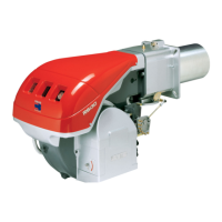
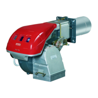
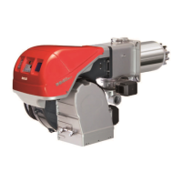
Lists the different burner models offered by the manufacturer.
Classifies burners based on country of destination and gas category.
Presents key technical specifications like output, fuel, and noise levels.
Details electrical supply requirements, motor specifications, and ignition transformer data.
Provides dimensional data for various burner models with illustrations.
Illustrates burner output ranges based on combustion chamber pressure and thermal power.
Describes the test boiler specifications used for obtaining firing rate data.
Lists the components supplied with the burner as standard equipment.
Explains how to adjust firing rates based on altitude and air temperature.
Identifies key components of the burner through numbered diagrams.
Details the function, installation, and safety notes for the REC 27.100A2 control box.
Shows the sequential steps and timing of burner operation phases.
Explains how to use the operator panel for programming and diagnostics.
Describes the technical specifications and installation of servomotors.
Emphasizes crucial safety precautions to be taken during burner installation.
Provides guidance on safely handling the burner during transport and installation.
Outlines essential checks before installation, including consignment and burner characteristics.
Specifies the allowed and prohibited operating positions for the burner.
Details steps for preparing the boiler, including boring the plate and blast tube length.
Guides the correct positioning of the probe and electrode for optimal performance.
Explains the procedure for securely mounting the burner to the boiler.
Describes how to adjust the combustion head for optimal air and gas flow.
Details the steps to reassemble and close the burner after adjustments.
Covers safety precautions and components related to the gas supply system.
Discusses gas train type approval and installation requirements.
Provides instructions for installing the gas train, including safety checks.
Presents data on gas pressure and related output for various burner models.
Outlines safety instructions and procedures for electrical wiring connections.
Highlights essential safety measures for the initial burner start-up.
Lists the necessary adjustments to be made before attempting ignition.
Describes the procedure for powering up the burner and verifying motor rotation.
Explains how to adjust firing output, maximum, and minimum burner settings.
Details the calibration process for air and gas pressure switches.
Explains how to access and use the Info mode for system information.
Guides on how to modify burner parameters using the operator panel.
Describes how to access Service mode for error logs and technical information.
Explains how to access and navigate the Parameter mode for configuration.
Provides a step-by-step guide for the burner start-up process.
Details how to set and adjust modulation curve points for fuel and air servomotors.
Explains the CALC function for recalculating modulation curve points.
Outlines the process for backing up and restoring burner parameters.
Lists all available parameters with their numbers, descriptions, and settings.
Details various checks required on the burner's operating mode and components.
Stresses safety precautions that must be followed during maintenance operations.
Outlines the recommended maintenance schedule and checks.
Explains how to measure the ionisation current for flame detection verification.
Details how to measure air and gas pressure at the combustion head.
Describes procedures for cleaning the combustion head, fan, and burner components.
Provides instructions for safely opening the burner for inspection or maintenance.
Details the procedure for reassembling and closing the burner.
Lists error codes, their meanings, and recommended troubleshooting measures.
Lists available long head kits with their specifications and codes.
Lists available spacer kits with their specifications and codes.
Lists available continuous purging kits with their codes.
Lists available soundproofing chamber kits with their specifications and codes.
Details kits for modulating operation, including power regulators and probes.
Lists available differential switch kits with their codes.
Lists available gas flange kits with their codes.
Lists kits for LPG operation, including burner models, output, and combustion head type.
Lists kits for town gas operation, including burner models and combustion head type.
Lists software interface kits for service level operations.
Lists Modbus interface kits with their models and codes.
Lists head kits for flame inversion boilers with specifications and codes.
Lists PVP kits for gas trains with their types and codes.
Provides a list of available layout diagrams within the appendix.
Explains how references and coordinates are indicated in the electrical diagrams.
Explains the meaning of symbols and abbreviations used in the wiring diagrams.