25
20068428
Installation
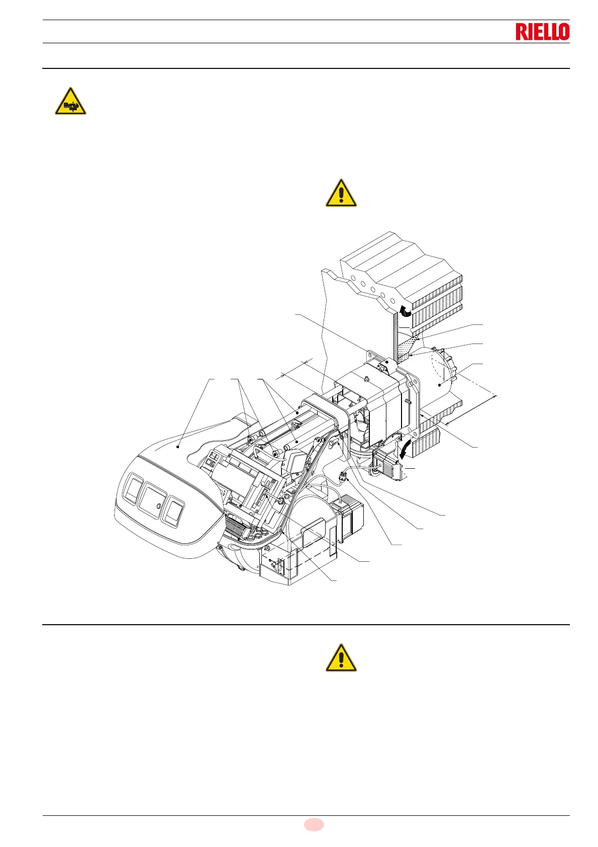
5.7 Securing the burner to the boiler
Separate the combustion head from the rest of the burner, as in
Fig. 16; proceed as follows:
loosen the 4 screws 3) and remove the hood 1);
remove the screws 2) from the two guides 5);
disconnect the plug 14), unscrew the grommet 15);
disconnect the socket from the maximum gas pressure
switch;
remove the two screws 4);
pull back the burner on the guides 5) by about 100 mm;
disconnect the probe and electrode leads, then unthread the
burner completely from the guides.
Once this operation has been carried out:
fix the flange 9) to the boiler plate, interposing the supplied
insulating gasket 8).
Use the 4 screws supplied, with a tightening torque of 35 ÷
40 Nm, after protecting their thread with anti-seize products.
5.8 Combustion head adjustment
At this point of the installation, the combustion head is fixed to the
boiler as shown in Fig. 14.
It is therefore especially easy to adjust, and this adjustment de-
pends only on the maximum output of the burner.
Two adjustments of the head are foreseen:
–air
–gas
In the diagram (Fig. 17) find the notch at which to adjust both air
and central gas/air.
Air adjustment
Rotate the screw 2)(Fig. 18) until the notch you have found
corresponds with the front surface 1) of the flange.
Provide an adequate lifting system of the burner.
The seal between burner and boiler must be air-
tight; after the start-up, check there is no leakage
of flue gases into the external environment.
100
mm
5
9
12
11
8
3
4
21
L
10
13
13
3
15
14
To facilitate adjustment, loosen the screw
3)(Fig. 18), adjust and then lock.