SAFE 4 10
020911
bis Kategorie 4; SIL3; PLe
erreichbar
up to category 4; SIL3; PLe
reachable
bis Kategorie 4; SIL3; PLe
erreichbar
up to category 4; SIL3; PLe
reachable
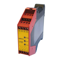
Beispiel 5: Zweikanalige Schutztür-
überwachung (mit Querschlusss-
sicherheit).
Werden die Schutztürschalter S1 und S2
geschlossen, bleiben die Ausgangskon-
takte unverändert. Erst mit Freigabe wird
das Gerät aktiviert. Die Kontakte13-
14,23-24 schließen. Beim Öffnen des
Schutztürtasters fallen die Kontakte un-
verzögert in ihre Grundstellung zurück.
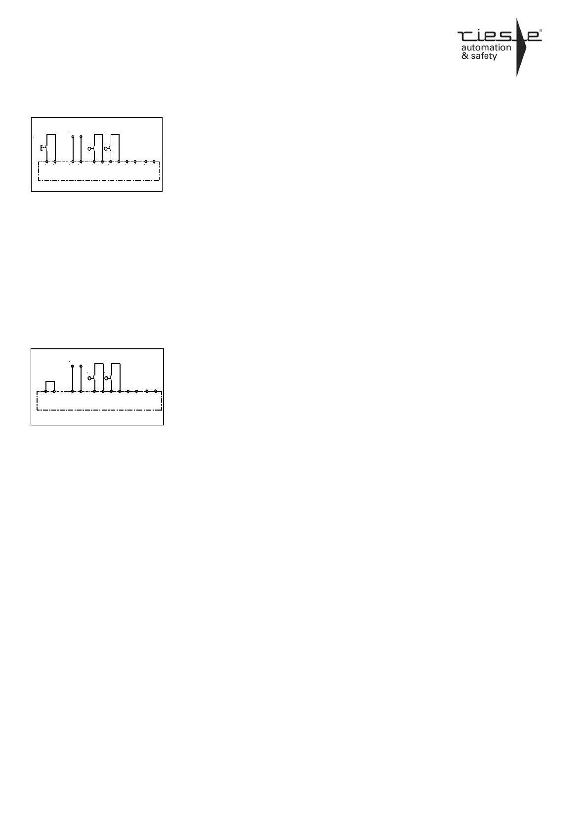
Beispiel 6: Zweikanalige Schutztür-
überwachung mit automatischer Akti-
vierung und Querschlusssicherheit.
Nur bei SAFE 4.1
In diesem Beispiel erfolgt die Aktivierung
des Gerätes automatisch, da S33 und
S34 überbrückt sind. Wird der Schutztür-
schalter geschlossen, schließen die Kon-
takte 13-14, 23-24 und 33-34. Beim Öff-
nen des Schutztürtasters fallen die Kon-
takte unverzögert in ihre Grundstellung
zurück. Dieses Anwendungsbeispiel ist
nur mit der Gerätevariante SAFE 4.1
ohne Überwachung der START-Taste
möglich.
Der automatische Start erfolgt schon
beim Anlegen der Versorgungsspan-
nung.
Verdrahtungshinweis für die Ausgangs-
klemmen 13-14, 23-24,
33-34 und 41-42:
Es sollte die Spannung (L-Leiter bzw.
24V DC), und nicht NULL, über die Aus-
gänge geschaltet werden um Erd- / Mas-
se- schlüsse erkennbar zu machen.
Zur Schonung der Kontakte empfehlen
wir ein RC-Glied parallel zum Verbrau-
cher zu schalten.
* Kategorie 4 nur bei Verwendung von
zwangstrennenden Schaltern und Verle-
gung der Kabel in getrennten Mantellei-
tungen.
Example 5: Dual-channel protection
door monitoring with opposite polarity
between channels.
If the safety gate switches are closed, the
output contacts remain unchanged. After
the release of the unit, the contacts 13-14
and 23-24 close. After opening the pro-
tection door switches the contacts return
to their normal position without delay.
Example 6: Dual-channel protection
door monitoring with automatic acti-
vation and with opposite polarity be-
tween channels.
Only SAFE 4.1
For this application the unit SAFE 4.1 /
SAFE 2.2 has to be used. The activation
works automatically, since the terminals
S33/S34 are bridged. If the protection
door switches close, the contacts 13-14,
23-24 close. After the opening of the
protection door switches the contacts
return to their normal position without
delay.
The automatic start already takes place
when the device is connected to the sup-
ply voltage.
Wiring hints for the output terminals
13-14, 23-24, 33-34 and 41-42:
The Voltages (for example L+ or 24 V
DC), and not GND, should be routed via
the terminals. This will help to recognise
shorts to GND or Earth.
Using R-C combination in parallel to
inductive loads can reduce wear out
of contacts.
* You have category 4, when using re-
stricted guided switches and lead the
wiring in separate coated cables.
24V AC/DC
A2(-)
S34S33
A1(+)
Freigabe/
release
S22S21 S12S11
23
13
S2 S1
41
33
41
33
24V AC/DC
A2(-)
S34S33
A1(+)
S22S21 S12S11
23
13
S2 S1
 Loading...