SAFE 4 4
020911
Power +
S21 S22 S11 A2
14 24 34 42
13 23 33 41
14 24 34 42
Channel
1 +
Channel
2 +
riese
Safe 4
A1 S34 S33 S12
13 23 33 41
Mechanische
Montage
mechanical
mounting
Elektrischer
Anschluss
Electronic
connection
Montage und Inbetriebnahme
Für eine sichere Funktion muss das Si-
cherheitsrelais in ein staub- und feuchtig-
keitsgeschütztes Gehäuse eingebaut
werden (IP54).
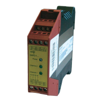
Montieren Sie das Sicherheitsre-
lais auf eine Normschiene.
Das SAFE4/4.1 (230VAC und 115VAC) ist für
den nicht angereihten Betrieb zugelassen.
Der Betrieb von mehreren Geräten oder mit
anderen Fremdwärmequellen im angereihten
Zustand ist nicht zugelassen und erfolgt auf
eigene Verantwortung. Bitte beachten Sie
hierzu die gültigen technischen Vorschriften.
Im 1.Quartail 2012 kommt eine Variante auf
den Markt, die diese Applikation auch erfüllt.
Führen Sie die Verdrahtung entspre-
chend des Verwendungszweckes durch.
Orientieren Sie sich dabei an den An-
wendungsbeispielen. Generell ist das
Sicherheitsrelais nach folgenden Anga-
ben zu verdrahten:
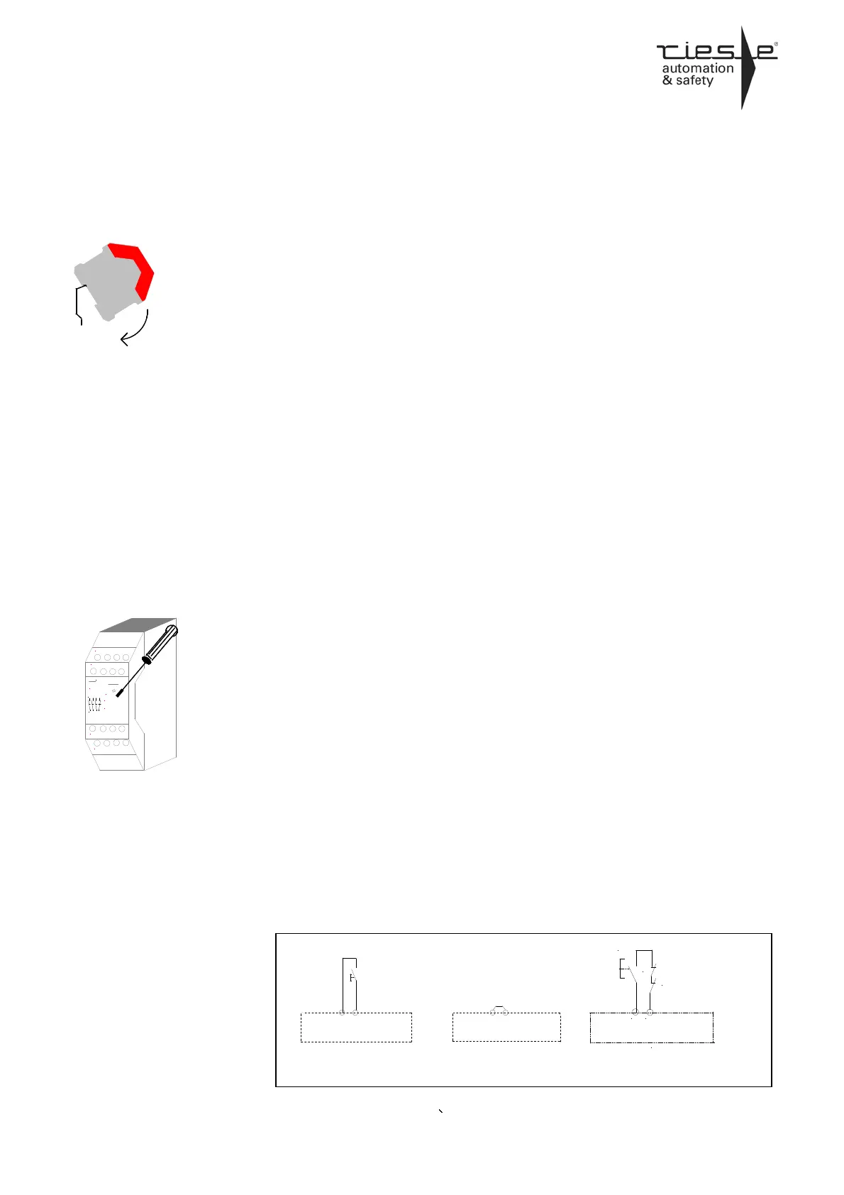
1. Aktivierungs- und Rückführungskreis
schließen
Automatische Aktivierung:
Brücken Sie die An-
Schlussklemmen
S33-S34
Bedingte Aktivierung:
Taster an S33-S34 an
schließen (keine Brücke
an S33-S34). Externe
Schütze werden in Reihe
zum START-Taster an
die Klemmen S33-S34
angeschlossen.
Mounting and opening
The unit should be panel mounted in an
enclosure rated at IP 54 or better, other-
wise dampness or dust could lead to
function impairment.
There is a notch on the rear of
the unit for DIN-Rail attachment.
The device SAFE4/4.1 (230VAC and
115VAC) is not approved for the operation
side by side. The operation of several devices
or with external heat sources side by side is
not approved and effects on your own risk.
Please notice the applicable regulations.
In the first quarter 2012 a new model will be
launched that meets this application.
Carry out the wire appropriate the use.
According to the examples of application.
General the safety-relay has to be wired
under following specifications:
1. Close the feedback control loop
and the activation circuit
Automatic activation:
Bridge S33-S34
Conditional activation:
Connect button on S33-
S34 (no bridge on S33-
S34). N.C. contacts of
external contactors are
wired in series with the
START-button at the
terminals S33-S34.
.
S34
automatischer Start
without start control
SAFE 4.1
S33
S34
Start über Start-Taste
with start control
SAFE 4
S33
Start
S34
Start über Start-Taste und Anschluß
Maschinenfreigabekreise / Schützkontrolle
Start with start bottom and detection of external
conductors
S33
Start
K2 ext
K1 ext
 Loading...