SAFE 4 5
020911
Power +
S21 S22 S11 A2
14 24 34 42
13 23 33 41
14 24 34 42
Channel
1 +
Channel
2 +
riese
Safe 4
A1 S34 S33 S12
13 23 33 41
2. Eingangskreis schließen
Einkanalig: Schließen Sie
den Kontakt des Auslösee-
lementes an die positive Ver-
sorgungsspannung und die
Anschlussklemme A1(+) an.
Kategorie 4 nur bei Verwen-
dung von zwangstrennenden
Schaltern und Verlegung der
Kabel in getrennten Mantel-
leitungen.
Zweikanalig: Schließen Sie
die Kontakte des Auslösee-
lementes an S11-S12 und
S21-S22 an.
Die Verdrahtung der Versor-
gungsspannung ist abhängig
vom Gerätetyp (siehe Typen-
schild am Gerät).
3. Versorgungsspannung Uv:
24V AC/DC oder 115V AC, 230V AC
Einkanalig: Schließen Sie die
Versorgungsspannung
Uv (+) / L (Phase) über den
Kontakt des Not-Halt bzw.
Schutztürschalters an die
Klemmen A1(+). Schließen
Sie den Uv(-) / Uv
N
(Nulllei-
ter) direkt an die Klemme
A2(-) an.
Bei 115V und 230V-Geräten
muss der Erdanschluss an
S21 angeschlossen werden.
Zweikanalig: Schließen Sie
die Versorgungsspannung an
die Klemmen A1(+) und A2(-)
an. Bei 115V und 230V-
Geräten muss der Erdan-
schluß an S21 angeschlos-
sen werden.
Beachten Sie unbedingt die maximalen
Leitungslängen!
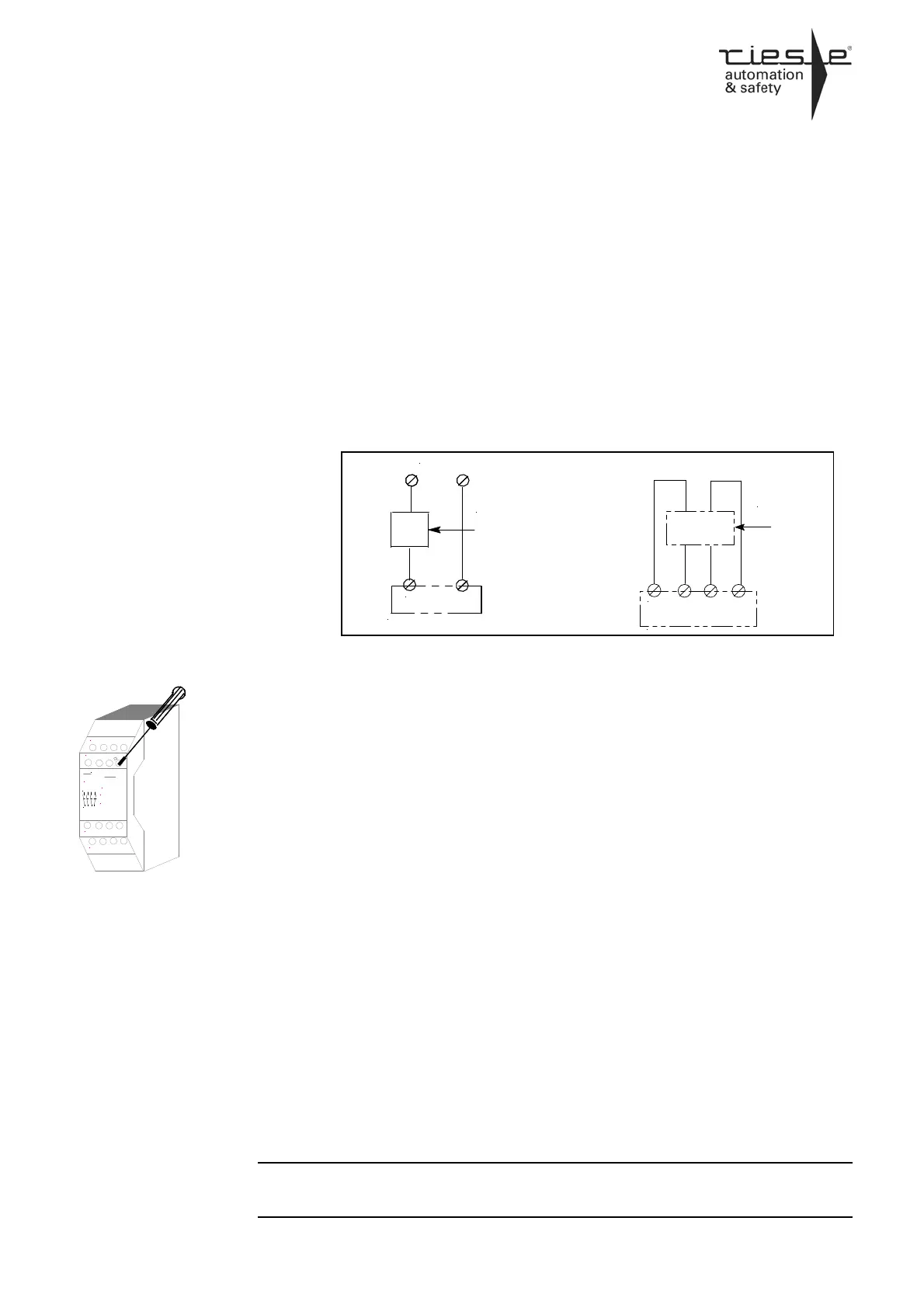
2. Close input circuit
Single-channel: Connect
contacts from trigger el-
ement to positive supply
voltage and A1(+). You
have category 4, when
using restricted guided
switches and lead the
wiring in separate coated
cables.
Dual-channel: connect
contacts from trigger el-
ement to S11-S12 and
S21-S22.
The wire of the supply voltage is de-
pendent on device-model (see type
plate on the device)
3. Supply voltage Uv:
24V AC/DC or 115V AC, 230V AC
Single channel: The Supply
voltage Uv (+) / L has to be
connected over the contact
from emergency stop / safety
gate monitoring to the termi-
nals A1(+) and Uv(-) / Uv
N
di-
rectly to terminal A2.
At 115V and 230V devices
the ground wire has to be
connected to S21.
Dual-channel: The supply
voltage has to be connected
to the terminals A1(+) and
A2(-).At 115V and 230V de-
vices the ground wire has to
be connected to S21.
Please note the max. lengths of the
cables!
zweikanalig / dual-channel
S11 S12 S22 S21
Auslöse-
element /
trigger
element
einkanalig / single-channel
A1 (+) A2 (-)
Auslöse-
element /
trigger
element
24 VAC/DC24 VAC/DC
 Loading...