B. Create (This option should be chosen, if no file existed
or the existing file has a different name from that pre-set
in the “filename” in the Mini SD card inserted in ELC-
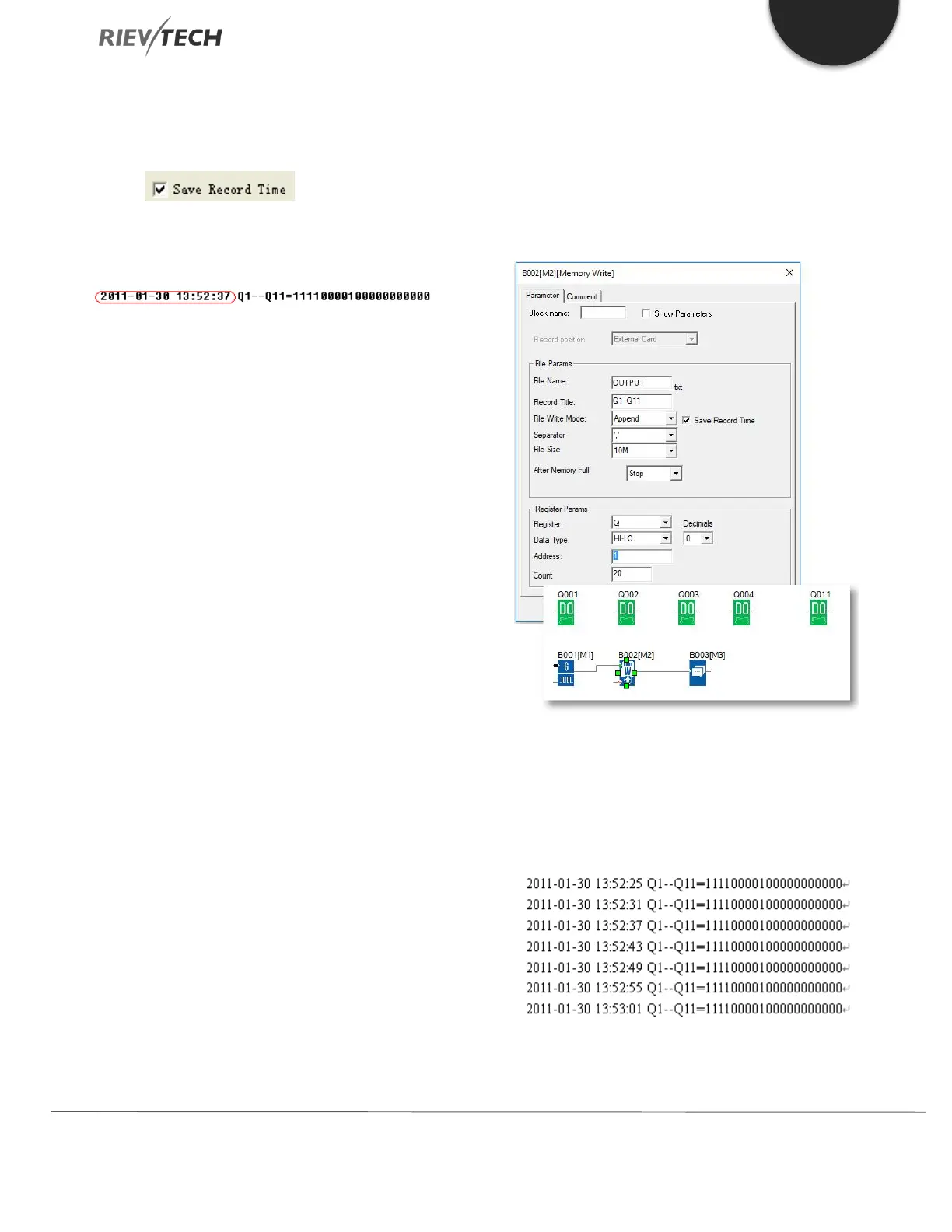
MEMORY If this box has been
ticked, the file content will show the time when the data
starts to be recorded.
4. Separator
Such separator shall be required while more than one
analogue values would be stored and displayed for easier
observation and convenient analysis.
5. File Size
Sets the size of the file to be stored.
6. After memory Full
Two options can be selected after the memory is full (it
means the relative file has reached its pre-configured size),
one is to over-write and the other is to stop recording.
7. Register params:
This section is for register’s parameters setting. The
register includes the following choices:
I – Digital Inputs
Q - Digital Outputs
F - Digital Flag
M – Digital Block Statuses
AI - Analogue Inputs
AQ - Analogue Outputs
AF - Analogue Flag
AM – Analog Blocks Values
EXAMPLE:
Please refer the property dialogue box of B002, it can
record the output status. The start address is from 1 and
it must record the 20 outputs with continuous addresses.
And the record file shows below:
Per program, every 6 seconds the record will do once, and
the Q1, Q2, Q3, Q4, Q11 will be all “ON”. You can see the
 Loading...


