Tips on Connecting Blocks
1. Hover the mouse pointer over a block and the type of
block will be shown. Hovering over the input pins of a
block will show the name of each pin.
2. To make it easier for you to connect blocks, a blue
frame around the mouse pointer pops when it is in the
correct position over the target pin.
Rules for Connecting Blocks
The following rules apply to the connection of blocks:
1. You can connect a single input to multiple outputs.
2. You cannot connect multiple inputs to a single output.
Special function blocks also have green "connectors".
These do not represent connecting pins but are used
instead for assigning the parameter settings.
3. Analogue I/O cannot be connected to Digital I/O.
Delete Function Block or Delete Link
Sometimes changes are required, and blocks or links
need to be removed from your program. They can be
deleted as follows:
1. Click on block or link to delete with your mouse.
2. Press “Delete” on the keyboard or click the right mouse
button and select option “Delete” from the pop-up menu.
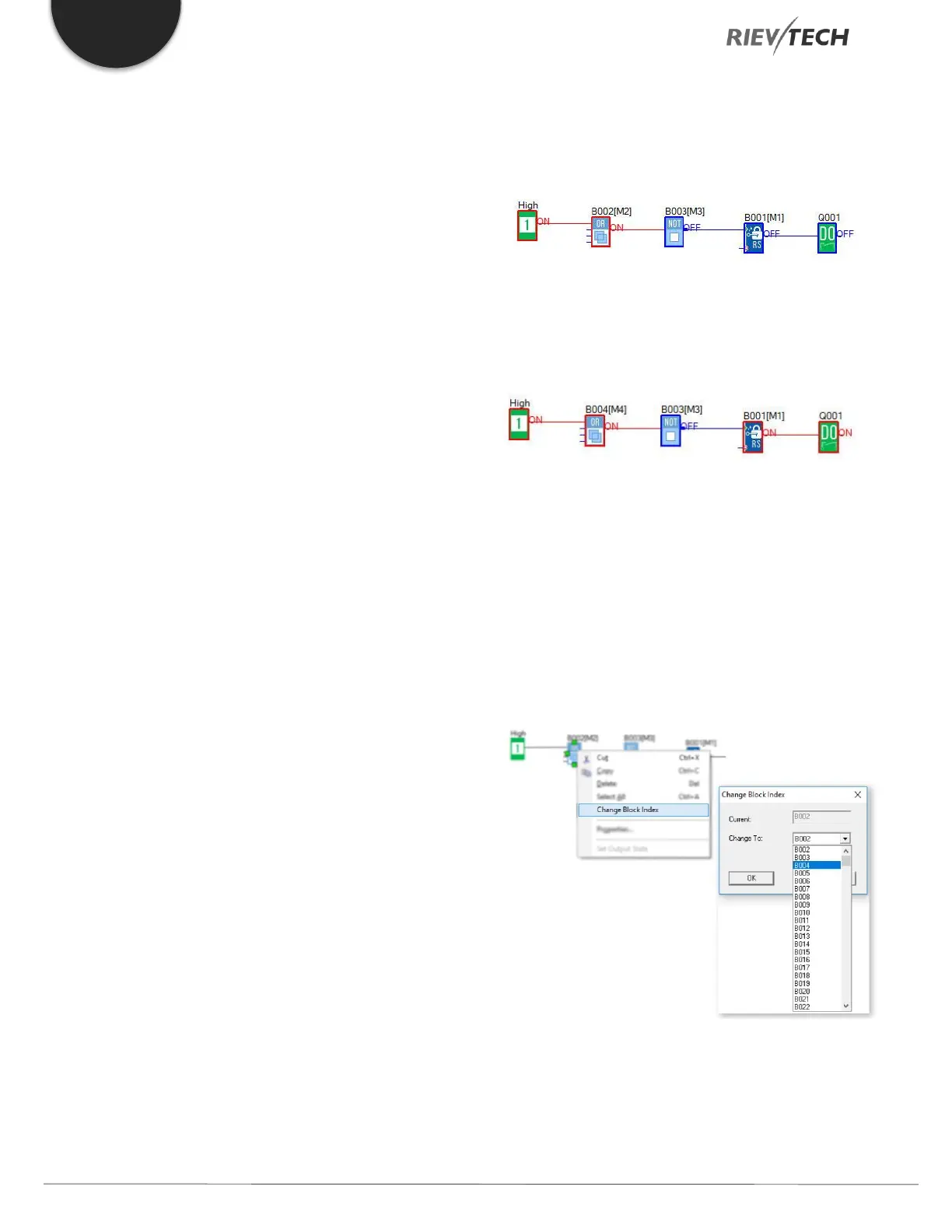
Change Block Index
In a program cycle, program blocks are executed in
order, starting with the smallest and ending with the
largest.
For example, in the program below, the run sequence is
B001, B002, B003, so the output Q1 will NEVER turn On
because B001 is executed before B002.
If we change B002 to B004, then Q1 will switch On as
expected. The program run sequence is B001, B003, and
B004.
You can change the block number by right-clicking on
the block and selecting the “Change Block Index” option,
then select another block number. Note you cannot select
a block number that is already used by another block in
the program.
Program Simulation
xLogicsoft is used to create/edit a function diagram
program and can also function as a simulation tool.
 Loading...


