CPU
18
I/O
Expandable
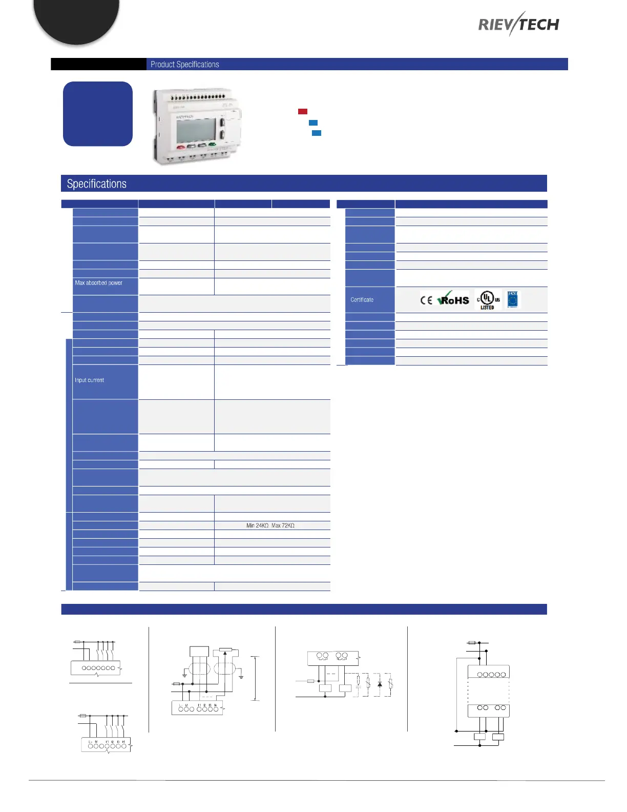
PR-18
Model: PR-18AC-R
AC
Model: PR-18DC-DA-R
Model: PR-18DC-DA-RT
DC
DC
Item PR-18AC-R PR-18DC-DA-R PR-18DC-DA-RT
Nominal voltage AC 110V-240V
AC 85 - 265V
47-63Hz
-
-
1780VAC
49 mA (85VAC)
37 mA (265VAC)
Yes
DC 12-24V
DC 10.8-28.8V
-
Typ 5 ms
Max 0.25A
-
3.5W (10.8V DC)
4W (28.8V DC)
Power
Operating limits
The main
frequency range
Immunity from micro
power
Max startup current
Isolation voltage
Protection against
polarity inversions
Input No 12 (I1-IC)
12 (I1-IC)
-
AC 110-240V
AC 0-40V <0.03mA
AC 79-240V >0.06mA
-
-
-
-
-
6 (I1-I6) (0..10V DC)
DC 0-28.8V
Typ: 4 Hz
Contact or 3-wire PNP
Resistive
0 to 1: 120VAC:Typ. 50 ms
240VAC:Typ. 30 ms
1 to 0: 120VAC:Typ. 90 ms
240VAC:Typ.100 ms
Inputs
Inputs used as digital
Inputs used as analog
Digital input
Analogue input
Input voltage
Input signal 0
Input signal 1
Response time
Sensor type
Input type
Isolation between power
supply and inputs
Isolation between inputs
Measurement range
Input impedance
Input voltage
Resolution
Cable length
Accuracy at 25 癈
Accuracy at 55 癈
Isolation between analog
inputs and power supply
Yes
-
-
-
-
-
-
-
DC 0-10V
28.8V DC max
10bit 0.01V
?(Max 0.02)V
?(Max 0.04)V
-
10 m max shielded & twisted
Protection against
polarity inversions
Maximum counting
frequency
Item PR-18
Memory 1024 Functional Blocks / 13K Steps
10 years
10 years
Backup at 25 癈: 20 days,RTC accuracy : MAX ?S/day
0.6ms - 8.0ms
16 modules (PR-E-16)
1 RS232 port & 1 RS485 port (PR-E-RS485)
ModbusRTU/ASCII Master or Slave
General data
Data Retentivity
Program
Backup
RTC
Cycle time
Expansion
Communication
OperationTemp -20 癈 .. +55 癈
-40 癈 .. +70 癈
IP20
95*90*55 (Unit, mm)6DIN
35mm-DIN rail or screw for installation
Approx. 400g
StorageTemp
Protection
Dimensions
Installation
Weight
(I1-I6) <0.1mA / (I7-IC) <1mA @ < 5V DC
(I1-I6) >0.3mA / (I7-IC) >1.7mA @ > 8V DC
(I1-I6) 0.4mA / (I7-IC) 2.3mA @ 10.8V DC
(I1-I6) 0.5mA / (I7-IC) 2.6mA @ 12.0V DC
(I1-I6) 1.2mA / (I7-IC) 5.2mA @ 24V DC
(I1-I6) 1.5mA / (I7-IC) 6.3mA @ 28.8V DC
(I1-I6): 0 to 1:Typ. 1.5 ms
1 to 0:Typ. 1.5 ms
(I7-IC): 0 to 1:Typ. <1 ms
1 to 0:Typ. <1 ms
I1-I8: 4 Hz
I9-IC: 60 kHz
I/O circuit diagrams
[Digital Input - Power DC]
(1)
DC 12-24V
+
-
[Digital Input - PowerAC]
AC 110-240V
L N I1 I2 I3 I4
(1)
DC 12-24V
max 10m
2k2/0.5W
10k max
Ca/Ta
[DC analog inputs 0-10V - Power DC ]
(1)
+
-
+
-
[Relay Outputs]
L/+
(1)
(2)
(2)
Q2Q1
N/-
(1) - Fuse, circuit-breaker or circuit protector
(2) - Inductive load;
[Transistor Outputs PNP ]
DC 12-24V
(1)
+
-
DC 5-30V
+
-
L+
Q5 M
0.3A
Q6 M
M
 Loading...


