CPU
24
I/O
Expandable
PR-24
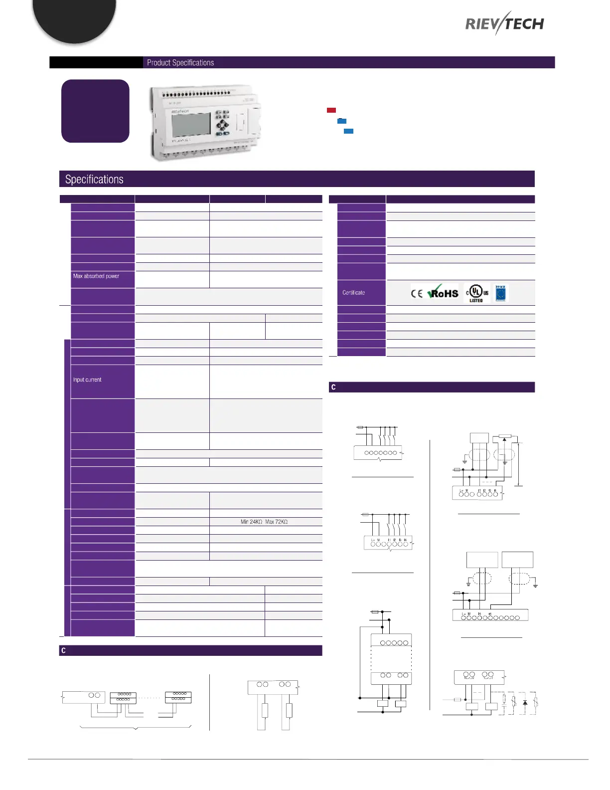
Model: PR-24AC-R
AC
Model: PR-24DC-DA-R
Model: PR-24DC-DAI-RTA
DC
DC
Item PR-24AC-R PR-24DC-DA-R PR-24DC-DAI-RTA
Nominal voltage AC 110V-240V
AC 85 - 265V
47-63Hz
-
-
1780VAC
49 mA (85VAC)
37 mA (265VAC)
Yes
DC 12-24V
DC 10.8-28.8V
-
Typ 5 ms
Max 0.25A
-
3.5W (10.8V DC)
4W (28.8V DC)
Power
Operating limits
The main
frequency range
Immunity from micro
power
Max startup current
Isolation voltage
Protection against
polarity inversions
Input No 14 (I1-IE)
14 (I1-IE) 12 (I1-I4)(I7-IE)
-
AC 110-240V
AC 0-40V <0.03mA
AC 79-240V >0.06mA
-
-
-
-
-
6 (I1-I6) (0..10V DC)
4 (I1-I4) (0..10V DC)
2 (I5-I6) (0..20mA)
DC 0-28.8V
Typ: 4 Hz
Contact or 3-wire PNP
Resistive
0 to 1: 120VAC:Typ. 50 ms
240VAC:Typ. 30 ms
1 to 0: 120VAC:Typ. 90 ms
240VAC:Typ.100 ms
Inputs
Inputs used as digital
Inputs used as analog
Current Inputs
Digital input
Analogue input
Input voltage
Input signal 0
Input signal 1
Response time
Sensor type
Input type
Isolation between power
supply and inputs
Isolation between inputs
Measurement range
Input impedance
Input voltage
Resolution
Cable length
Current input No
Analogue signal
Resolution
Accuracy at 25 癈
Cycle time for analog
value generation
Accuracy at 25 癈
Accuracy at 55 癈
Isolation between analog
inputs and power supply
Yes
-
-
-
-
-
-
-
-
-
-
-
-
DC 0-10V
28.8V DC max
10bit 0.01V
?(Max 0.02)V
?(Max 0.04)V
2 (I5-I6)
0/4?20mA current
0.02mA
0.05mA
Typ. 50 ms
-
10 m max shielded & twisted
Protection against
polarity inversions
Maximum counting
frequency
Item PR-24
Memory 1024 Functional Blocks / 13K Steps
10 years
10 years
Backup at 25 癈: 20 days,RTC accuracy: MAX ?S/day
0.6ms - 8.0ms
16 modules (PR-E-16)
1 RS232 port & 2 RS485 port (1 Built-in)
Modbus RTU/ASCII Master or Slave
General data
Data Retentivity
Program
Backup
RTC
Cycle time
Expansion
Communication
OperationTemp -20 癈 .. +55 癈
-40 癈 .. +70 癈
IP20
133*90*55 (Unit, mm)10DIN
35mm-DIN rail or screw for installation
Approx. 500g
StorageTemp
Protection
Dimensions
Installation
Weight
(I1-I4) <0.1mA / (I7-IE) <1mA @ < 5V DC
(I1-I4) >0.3mA / (I7-IE) >1.7mA @ > 8V DC
(I1-I4) 0.4mA / (I7-IE) 2.3mA @ 10.8V DC
(I1-I4) 0.5mA / (I7-IE) 2.6mA @ 12.0V DC
(I1-I4) 1.2mA / (I7-IE) 5.2mA @ 24V DC
(I1-I4) 1.5mA / (I7-IE) 6.3mA @ 28.8V DC
(I1-I6): 0 to 1:Typ. 1.5 ms
1 to 0:Typ. 1.5 ms
(I7-IE): 0 to 1:Typ. <1 ms
1 to 0:Typ. <1 ms
I1-I4, I7-I8, ID-IE: 4 Hz
I9-IC: 60 kHz
ircuit diagrams
ircuit diagrams
[Digital Input - Power DC]
(1)
DC 12-24V
+
-
[Digital Input - PowerAC]
AC 110-240V
L N I1 I2 I3 I4
(1)
DC 12-24V
max 10m
2k2/0.5W
10k max
Ca/Ta
[DC analog inputs 0-10V - Power DC ]
(1)
+
-
+
-
[Relay Outputs]
L/+
(1)
(2) (2)
Q2Q1
N/-
(1) - Fuse, circuit-breaker or circuit protector
(2) - Inductive load;
[Transistor Outputs PNP ]
DC 12-24V
(1)
+
-
DC 5-30V
+
-
L+
Q5 M
0.3A
Q6 M
M
[DC analog inputs 0-20mA - Power DC]
DC 12-24V
0/4-20mA
Device
0/4-20mA
Device
+
-
+ - +out
or
[RS485 Connection]
A+ B-
Built-in port RS485
Cable length max 1200m Total 20 stantions
A+ B-
A+ B- A+ B-
B-
A+
B-
A+
A+ B-
[DCAnalog Outputs - 0-10V / 0-20mA]
V1 M1
R R
Voltage Current
Voltage load:
PR Series:>650 Om
Current load:
PR Series:<500 Om
I1 M1
 Loading...


