4. Installing and Removing Rievtech Hardware
Dimensions
The dimensions of the Rievtech xLogic hardware is
compliant with DIN 43880.
xLogic can be “snap-mounted” to 35mm (EN 50022) DIN
rail or wall mounted.
Table 9 xLogic Dimensions
Always remove power whilst adding/removing an
expansion unit.
DIN Rail Mounting
The following procedure should be used to install/uninstall
your xLogic CPUs and expansion units on DIN rail.
4.2.1. Mounting Your Hardware
1. Hook the top of the xLogic CPU onto the DIN rail.
2. Push down the lower end to snap it into place. The
mounting catch MUST engage.
3. Hook the top of the xLogic expansion unit onto the
DIN rail.
4. Slide the expansion unit toward the CPU until they are
touching. Make sure the ribbon cable does not get caught
between it and the CPU.
5. Push down on the lower part of the expansion unit to
snap it in place, ensuring the mounting catch engages.
6. Lift-up the expansion port cover on the CPU.
7. Push the connector of the ribbon cable into the socket
on the CPU ensuring the correct alignment of the pins and
close the cover when done.
8. Repeat the procedure to add further expansion units if
required.
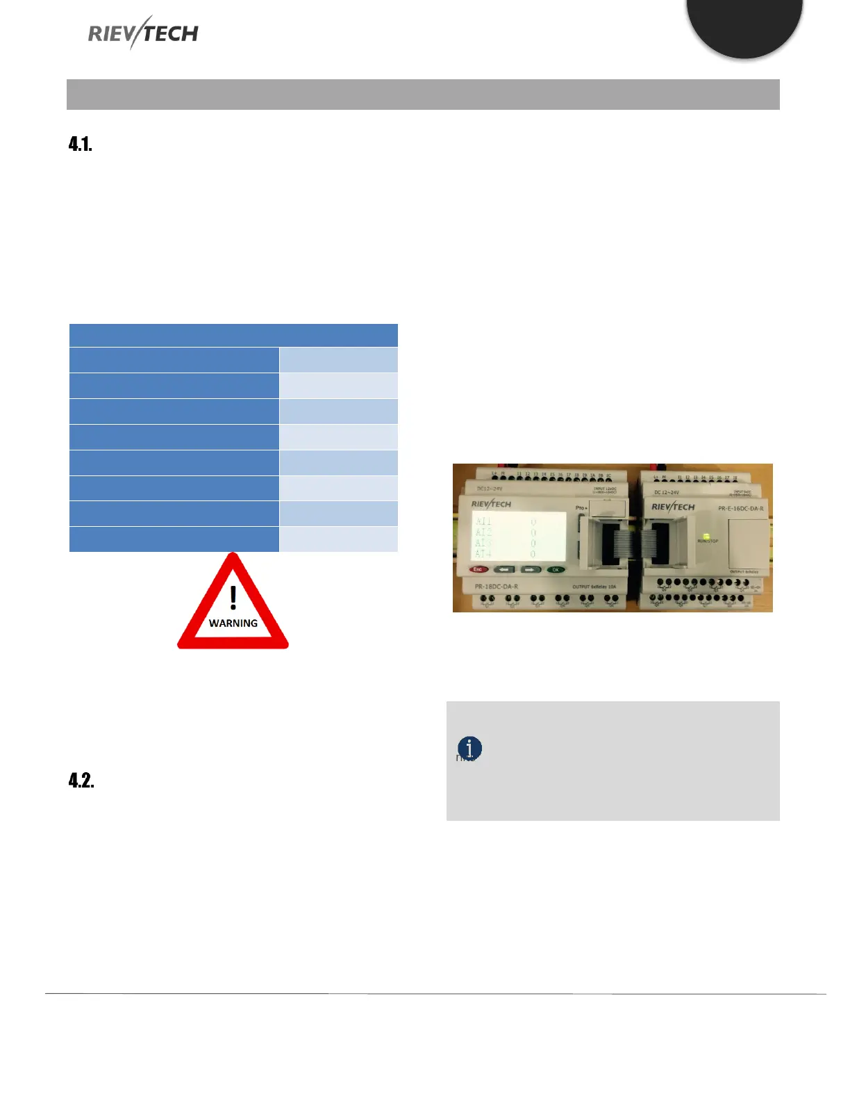
Figure 13 Connection the CPU with expansion
NOTICE:
If you need to install the CPU and expansion
units on different DIN rails, then you will need a PR-FLAT
expansion cable. The maximum distance between CPU
and expansion unit is 200 metres.
4.2.2. Removing Your Hardware
1. Insert a screwdriver into the eyelet at the bottom of
the sliding interlock and move the latch downwards.
2. Slide the expansion module to the Right.
 Loading...


