Compressor Operation – preset the automatic pressure gauge:-
Vehicle tyre inflation
Fig 1 Fig 2 + M - Fig 3 Fig 4
Remove the Velcro retaining strap and uncoil all of the power cable on the rear of the
compressor, ensuring all the cable is unwound. Insert the 12v DC plug into the 12v
socket. (Fig 1)
Remove the dust cap from the tyre valve and store in a safe place.
Carefully pull out the air hose from the side of the compressor. Screw the valve
connector clockwise onto the tyre valve. Ensure the valve is correctly connected but do
not over tighten. (Fig 2)
Press M button to select pressure gauge measurement from Bar, Kg/cm², Psi (Fig 3)
Caution: Only inflate product to the manufacturer’s specifications. Vehicle
tyre pressures can generally be found in the handbook, on the door pillar or on
the inside of the fuel filler cap.
The LCD display will show the current tyre pressure.
Hold + or – button for approx 5 seconds until LCD display flashes (Fig 3). Set the
required pressure using the + or – buttons then wait 2-3 seconds. The LCD will display
the current pressure value to which the tyre will be inflated.
Push the ON/ OFF for the compressor to start (Fig 3). When the pressure gauge reaches
the required value the compressor will automatically switch off and the LCD display will
show “OFF”.
If accidentally over inflated, deflate the tyre by depressing the deflation button on the air
hose (Fig 4). To check the pressure release the button, wait 2 seconds then check the
digital display for pressure reading. Repeat until the desired pressure is reached.
Unscrew the valve connector and reconnect to the next tyre. If the required pressure is
the same press the M button for the compressor to automatically inflate. If the pressure
is different, re set the compressor using the + and – buttons.
The ON/OFF button can be used to override the preset pressure value if required.
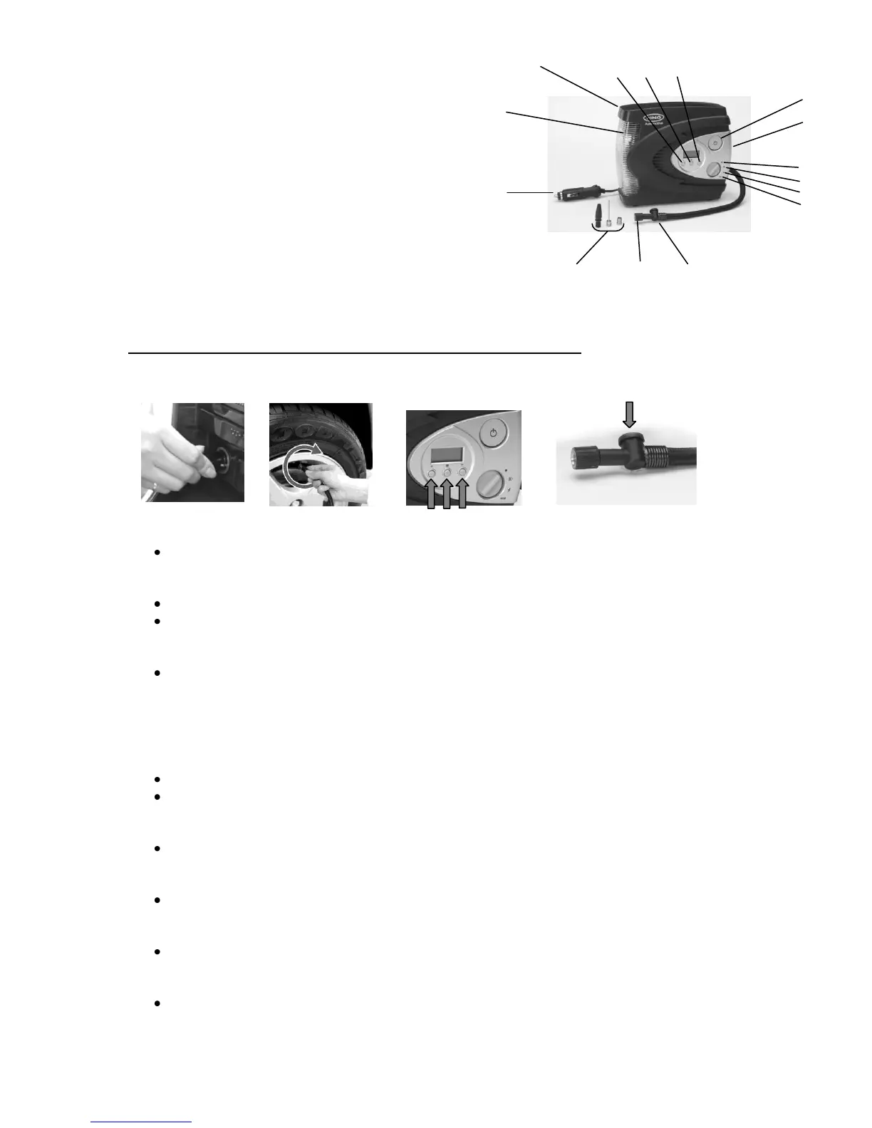
Control lay out
1) ON/OFF button
2) + push & hold button to increase preset pressure
3) M push to select pressure measurement. PSI, Kg/cm² or BAR
4) – push & hold to decrease preset pressure
5) Light switch position: A – off
B – WHITE LED light on
C – RED LED warning light flashing
D – RED LED warning light flashing SOS
6) LED light
7) Air hose stored in side compartment
8) Coiled power cable on rear
9) Fused 12v DC plug
10) Valve connector
11) Deflation button
12) 3x Valve adapters clipped on rear