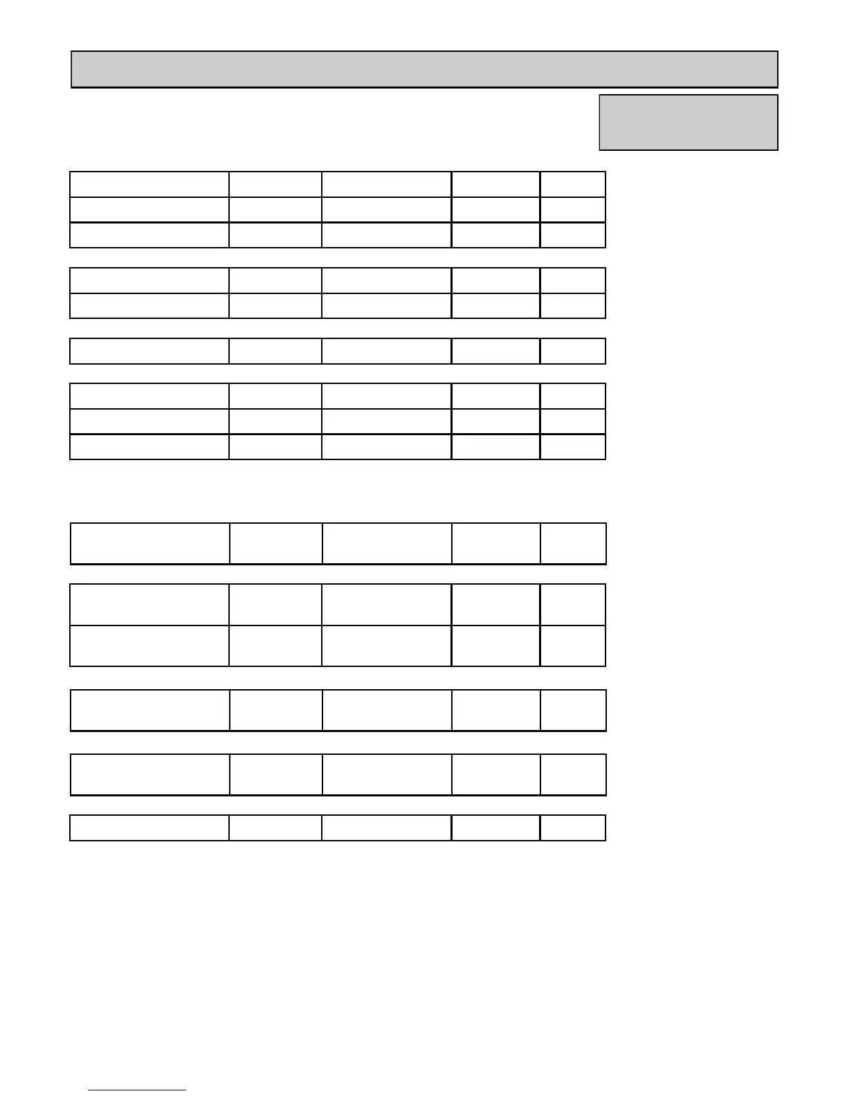
KB Series Electrical Diagnostic Points
RU80i/e, RU98i/e
Wire Color Voltage Resistance Connector # Pin #’s
Black - Red 11 ~ 13 VDC 5.5 ~ 6.2 K ohms L3 E10 - G7
Yellow - Black 4 ~ 7 VDC 1 ~ 1.4 Mega ohms B3 4 - 6
(QS) Water Flow Sensor:
Red - Pink 2 ~ 6 VDC 44 ~ 52 ohms G1 12 - 13
Yellow - Black 2 ~ 6 VDC 44 ~ 52 ohms G1 10 - 11
By-Pass Flow Control:
Grey - Grey
90 ~ 110 VAC
N/A C1 1 - 3
(IG) Ignition System:
Red - Black 6 ~ 45 VDC N/A L2 5 - 6
White - Black 5 ~ 10 VDC
9.72 ~ 9.75 K ohms
L2 3 - 5
Yellow - Black 11 ~ 13 VDC
4.02 ~ 4.05 K ohms
L2 4 - 5
(FM) Combustion Fan Motor:
Set your meter to the hertz scale. Reading across the white and black wires at terminals 3 and 5 you
should read between 60 and 420 hertz.
Red - White 11 ~ 13 VDC Below 1 Ohms
B8
B7
B1 - G8
Thermal Fuse / Overheat Switch:
White - White N/A
*See example on
page 11
E6 2 - 3
Blue - Blue N/A
*See example on
page 11
E6 4 - 5
Outgoing Water Thermistor:
Pink - Pink N/A
*See example on
page 11
E5 4 - 7
Heat Exchanger Temperature Thermistor:
White - White N/A
*See example on
page 11
E9 4 - 9
Inlet Thermistor:
Terminals J
10 ~ 13 VDC
1.5 ~ 3.0 K ohms J 1 - 2
Remote Control:
 Loading...