WOT4-E Instructions / WOT4-E Anleitung
6
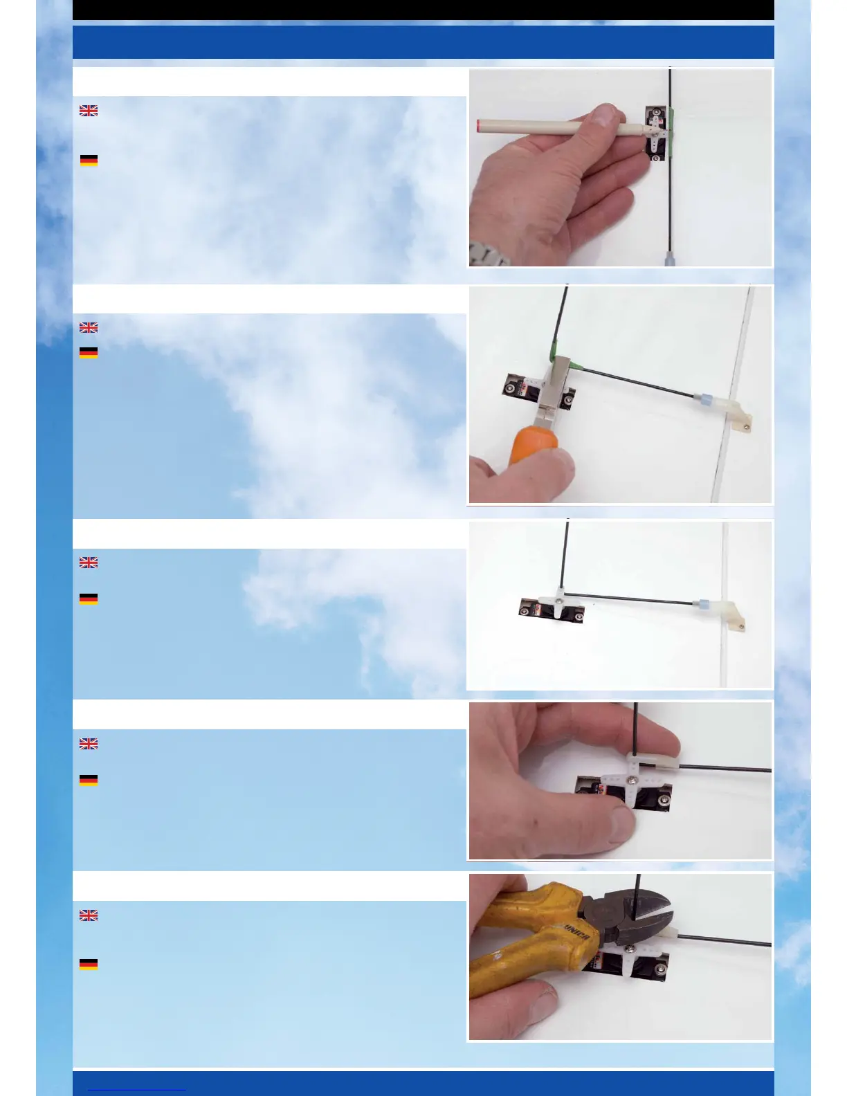
Locate a threaded wire aileron pushrod and attach a nylon clevis
to the end. Connect it to the aileron horn and mark the position the
control rod passes over the servo’s output arm.
Nehmen Sie das Querrudergestänge mit Gewinde und befestigen
am Ende einen Kunststoff Gabelkopf. Verbinden Sie diesen mit dem
Querruder Horn, und markieren die Position an dem das Gestänge
den Servoausgang kreuzt.
Stage 11 / Schritt 11
At the marked point, bend the pushrod up at 90°.
Biegen Sie das Gestänge an diesem Punkt um 90°.
Stage 12 / Schritt 12
Stage 13 / Schritt 13
Remove and slide the aileron servo horn over the wire and re-fit
to the servo.
Schieben Sie das Querruder Servohorn über den Draht, befestigen
Sie dies wieder am Servo.
Fit a moulded keeper and snap it onto the pushrod to retain it as
shown.
Befestigen Sie den Gabelkopf auf dem Gestänge, und sichern
diesen, wie gezeigt.
Re-fit the servo horn retaining screw and trim off the excess
pushrod wire using side cutters. Repeat the procedure for the second
aileron in exactly the same way.
Befestigen sie die Schraube des Servo Horns, und schneiden das
überschüssige Gestänge mit einem Seitenschneider ab. Wiederholen
Sie dieses Verfahren auch für das zweite Querruder.
Stage 14 / Schritt 14
Stage 15 / Schritt 15