6
Insulation Resistance Measurement
ON
50V
100V
250V
500V
1KV
V
R
M
W
Note
During Insulation resistance measurement the symbol
flashes as long as the high voltage is present at the terminals
5. Insulation Resistance Measurement (MW)
5.1. Preparation for measurement
· Select the required "Test Voltage (50V/100V/250V/500V/1000V)"
by changing the "Function Selector Switch".
· Connect the test probes firmly to the circuit under test.
Note !
Insulation resistance can only be measured at voltage free
object. Hence the circuit under test must be switched off,
de-energized and isolated before carrying out any insulation
resistance measurement.
When measuring high-ohmic insulation resistance do not
touch the measurement cables.
If an interference voltage > 25V is present within the
system, insulation resistance measurement is disabled.
The instrument defaults to the default voltmeter and
displays the value of the interference voltage on the LCD.
Also the instrument indicates this additionally by an
acoustic signal.
HIGH-VOLTAGE
Do not touch the conductive ends of the test probes
after insulation resistance measurement has been
activated at the instrument.
A current with a value of 2 mA (limited by the instrument)
may flow over your body, and although this is not life
endangering, the electric shock is distinctly perceptible.
If you are taking a measurement at a capacitive device under test, for
example a cable, it may be charged with as much as
1000V, depending upon the selected nominal voltage. Touching the
device under test after measurement may be life endangering in
such cases!
5.2 Insulation resistance measurement
The instrument provides flexibility for both manual and
continuous (for a pre-selectable time) insulation - resistance
measurement.
5.2.1 Manual Insulation resistance measurement :
In manual Insulation resistance measurement, Press and hold "TEST"
key until the display has stabilized. Insulation resistance measurement is
ended when the yellow TEST key is released. Instrument will continue to
show the last reading for few seconds even after releasing the "TEST
key".
Note !
The instrument's batteries are depleted during insulation
resistance measurement. Only press and hold the TEST key
as long as it is necessary to take the reading in the manual
measurement mode. Continuous measurement as described
below should be performed, if absolutely necessary.
7
RISH
Insu
20
400
100kM
600
10kM
ON
200
1MG
800
1kM
G
100k
1000
10MG
8
L
L
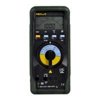
3. Selecting Measuring Functions
The desired measuring function is selected with the Function selector switch.
4. Liquid Crystal Display
4.1 Digital Display
The digital display shows the measurement value and decimal point. The
selected measuring unit and function are displayed.
4.2 Analog Display
The analog indication gives the dynamic performance of a moving coil
mechanism. This is especially advantageous for the observation of
measurement value fluctuations and for calibration procedures.
4.3 Back Lit
The instrument is provided with user selectable Back-lit for taking
measurements in poor lighting conditions / dark areas. Refer section 11
on page 14 for switching ON / OFF the backlit from the menu.
By pressing " " and "ON/OFF" key simultaneously
during power ON, the back-lit can be switched ON.
CE