Rittal fan-and-filter unit assembly and operating instructions 15
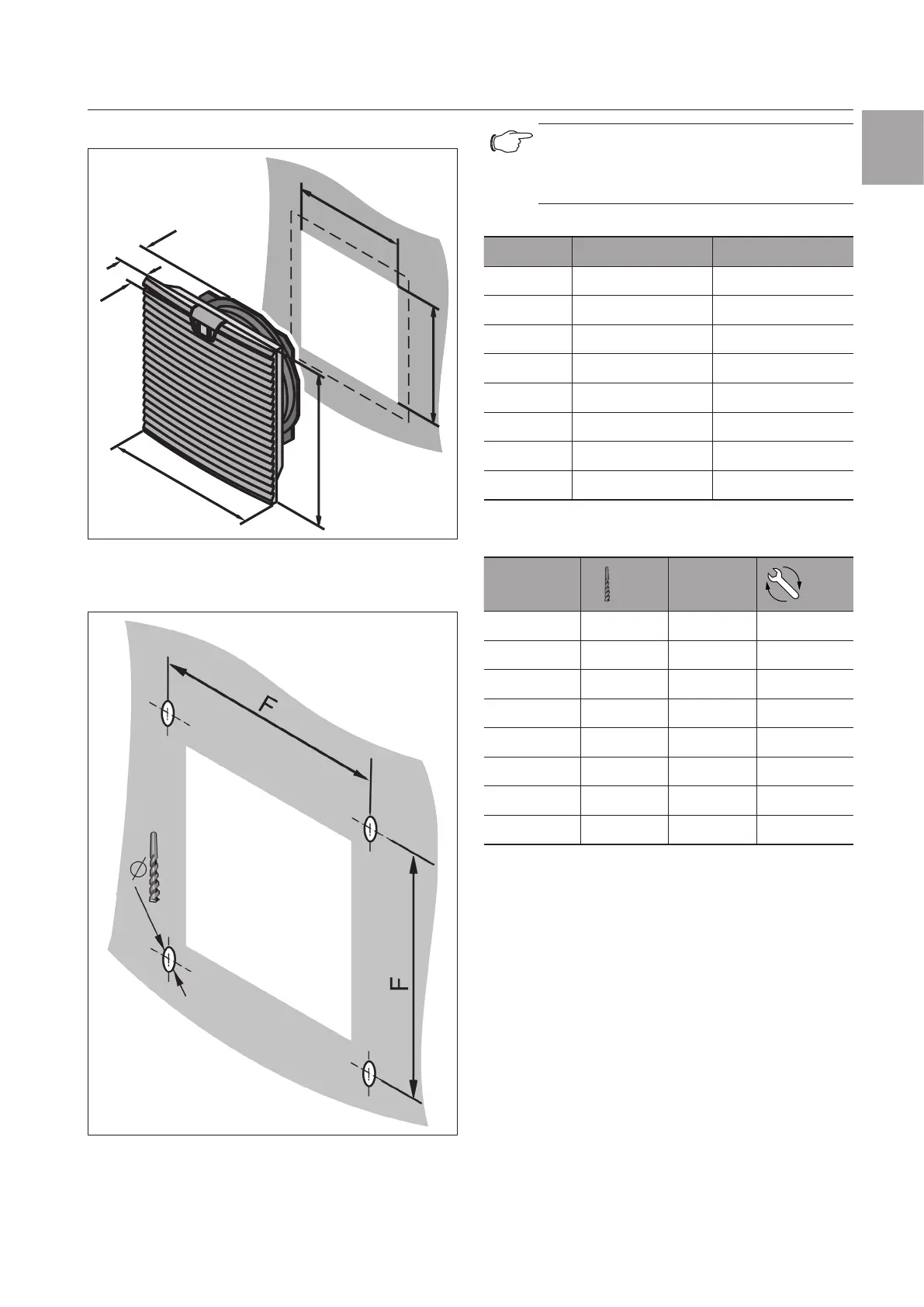
Cut-out/drilling dimensions
EN
11 Cut-out/drilling dimensions
H2
B2
H1
B1
T2
Fig.10: Cut-out dimensions
B = width; T= Depth
Fig.11: Drilling pattern
Note:
The cut-out must be increased by 1mm
each side for wall thickness above 2.5mm
(see accompanying drilling template).
Model No. B2 x H2 mm T2 mm
3237.xxx 92 x 92 43
3238.xxx 124 x 124 58.5
3239.xxx 177 x 177 90
3240.xxx 224 x 224 107
3241.xxx 224 x 224 107
3243.xxx 292 x 292 118.5
3244.xxx 292 x 292 130.5
3245.xxx 292 x 292 130.5
Tab. 7: Cut-out dimensions
Model No.
Ø
mm
F mm
Nm
3237.xxx 3.5 100.5 1
3238.xxx 3.5 132.5 1
3239.xxx 4.5 185 1
3240.xxx 4.5 234 2
3241.xxx 4.5 234 2
3243.xxx 4.5 302 3
3244.xxx 4.5 302 3
3245.xxx 4.5 302 3
Tab. 8: Drilling dimensions
12 EMC fan/outlet filter
To achieve EMC protection, the EMC fans and EMC
outlet filters should be snapped into the mounting
cut-out and screw-fastened using the screws supplied.
Next, the four contact foils should be stuck on all-
round between the fan-and-filter unit and the inside of
the enclosure as shown in the following illustration.
 Loading...